Ford Taurus C191 60-Pin Connector Pinout Diagram - Circuit Numbers & Wire Colors

Reference · 1992-1995 TaurusAll 37 wiring diagrams
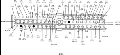

Wiring diagram of connector C191 showing each terminal pin with its color-coded circuit number.
Part of 1992-1995 Ford Taurus Wiring Diagrams
This document is a pinout diagram of electrical connector C191, a 60-pin connector drawn with three rows of pins (1-20, 21-40, 41-60). Each pin position is labeled with a Ford-style circuit number and wire color abbreviation (e.g., 37 (Y), 810 (R/LG), 150 (DG/W), 359 (GY/R), 923 (O/BK), 60 (BK/LG)). Wire color codes used include Y (yellow), R (red), LG (light green), DG (dark green), GY (gray), BR (brown), O (orange), T (tan), PK (pink), LB (light blue), DB (dark blue), W (white), BK (black), and P (purple) in various combinations. Two pins carry alternate circuits marked with asterisks: 224 (T/W) / *480 (P/Y) and 912 (W/R) / *971 (PK/BK). Three pin positions are shown as solid black (unlabeled/not used). The diagram was uploaded to a 1993 Ford Taurus gallery alongside other Taurus reference scans; on that platform C191 is the 60-pin EEC (engine control module) harness connector. A reader can use this diagram to identify which circuit number and wire color corresponds to each of the 60 pin cavities when probing or repairing the connector, though the document itself carries no year, model, or component name beyond the connector designation C191.
Is this accurate? Sign in to help verify it.
Frequently asked questions
- What connector is shown in this diagram?
- The diagram is labeled C191 and shows a 60-pin connector with pins numbered 1 through 20 (top row), 21 through 40 (middle row), and 41 through 60 (bottom row).
- What circuit and wire color is on pin 21 of connector C191?
- Pin 21 (left end of the middle row) is labeled circuit 68 with an O/BK (orange/black) wire.
- Are any pins in C191 unused?
- Yes: three pin positions are drawn as solid black circles with no circuit label: one in the middle row and two in the bottom row (between pins 41 and 44).
- Do any pins have alternate circuit assignments?
- Yes. Two bottom-row pins show asterisked alternates: 224 (T/W) with *480 (P/Y), and 912 (W/R) with *971 (PK/BK).
- What wire color is circuit 60 in this connector?
- Circuit 60 appears twice, labeled BK/LG (black/light green), at the right end of the middle row (pin 40) and at the right end of the bottom row (pin 60).


No comments yet.