
This document page details the electrical system for a diesel engine's start/glow plug control.
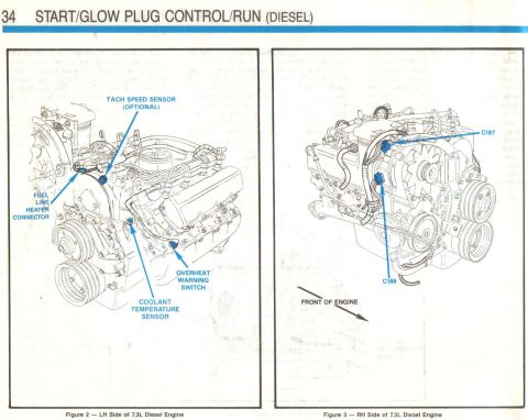
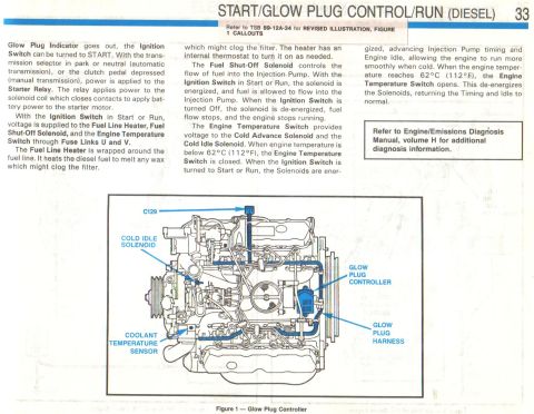
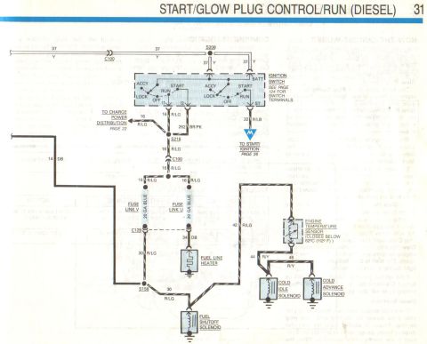
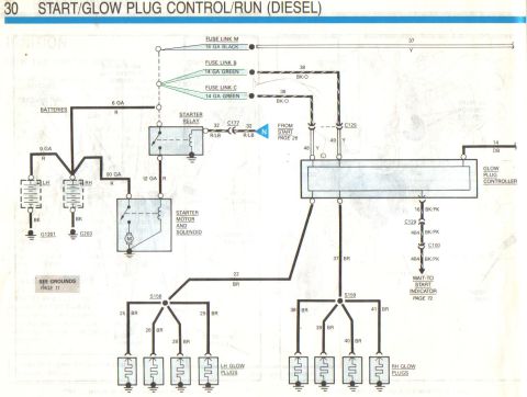
32 START/GLOW PLUG CONTROL/RUN (DIESEL) HOW THE CIRCUIT WORKS The Diesel Start/Glow Plug Control Circuit applies powertotheGIowPlugsthch heatthe combustion chambers, 50 that the cold diesel engine can be started. Glow Plug Control The solid state Glow Plug Controller Is at- tached to the top of the engine block. It controls glow plug pre-glow and after-glow time. The Glow Plug Controller controls the clrcuit's opera tion by sensing engine temperature, glow plug voltage, and after-glow voltage from start/run clrcult. When the Ignition Switch is turned to RUN, voltage Irom Fuse Link V is applied through the Glow Plug Controller to the Glow Plugs Walt to Start Indicator Lamp. The glow plugs are heated from zero to Ilfteen seconds. depending on engine coolant temperature. After thls time, the controller cyc- ling swltoh opens and turns OFF the Glow Plugs Wait to Start Indicator Lamp. The Glow Plugs are now warm enough tor the engine to be started. At the same time the Ignition Switch ls turned to Run, voltage from Fuse Llnk V ls applied to the After-Glow Tlmer (located Inside the Glow Plug Controller). The After-Glow Tlmer cycles the Glow Plugs for up to two minutes, depending on engine temperature. The After-Glow Timer then opens. The Walt to Start Indicator Lamp will not light during AfterGlow period. II the ignition switch is turned OFF, it can be turned ON immediately and the Glow Plug heating cycle will start again. Diesel Start/Run The diesel engine uses two batteries to pro vide extra power for starting and glow plug heating. Power is applied from the batteries through heavy gauge wires to the Starter Sole- noid in the Starter motor assembly. When the COMPONENT LOCATION Cold Advance Solenoid . . Cold Idle Solenoid Engine Temperature Switch Fuel Line Heater , . , . . Fuel Shut-Off Solenoid . . . Fuse Link B, C, M . , FuseLinkU,V.... .. Glow Plug Controller . . . . Glow Plug indicator Starter Relay ........... Page- Flgure In injection pump .................. On injection pump ............ At left front end of engine ...... RH side at engine In injection pump . Near starter relay , . RH fender apron ............. LH rear top of engine ........... In diesel warning lamp module . . FIH tender tions and locations. Refer to the Location Index in the back of the manual for connector, ground, and splice descrip- TROUBLESHOOTING HINTS CONDITION POSSIBLE CAUSE ACTION . No Glow Plugs operate ' No Volta e at Y wire con nector o Glow Plug Con- - Check Fuse Links B and C and check wiring troller - One Glow Plug does not - No voltage at BR wire of I Check for open in ER wire operate Glow Plug
Comments
More from this build


No comments yet.