Ford Horn Relay Wiring Diagram & Horn Switch Bypass - High/Low Pitch Horns
Reference · 1987-1991 F-150All 8 wiring diagrams
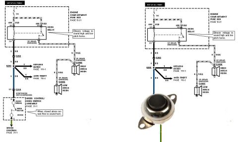
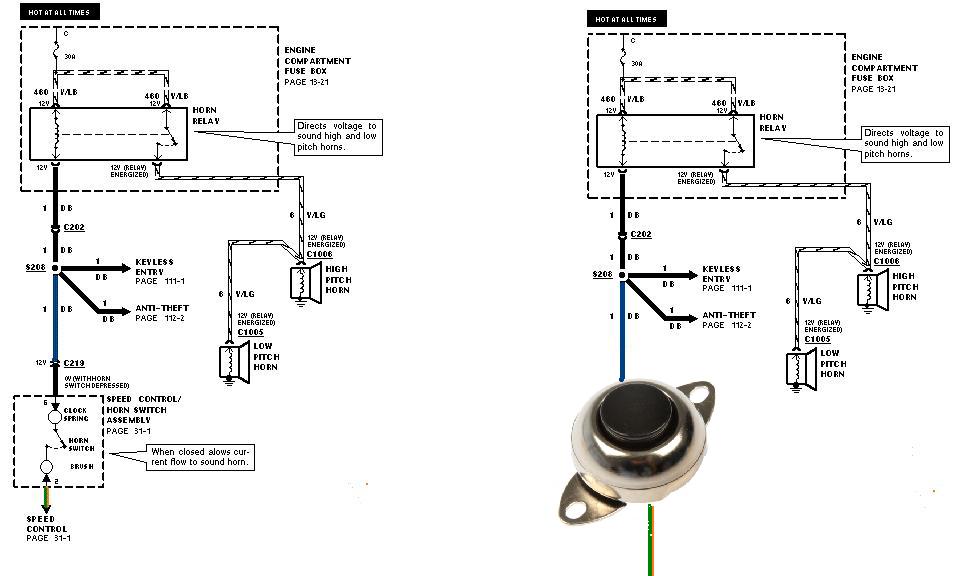
Wiring diagram of the horn circuit showing the horn relay, fuse box, keyless entry and high and low pitch horns.
Part of 1987-1991 Ford F-150 Wiring Diagrams
This document is a two-panel horn circuit wiring diagram, apparently taken from a Ford EVTM (Electrical & Vacuum Troubleshooting Manual) and modified to show a horn switch bypass. The left panel shows the factory horn circuit: a hot-at-all-times 30A fuse in the engine compartment fuse box (page 13-21) feeds the horn relay via circuit 460 V/LB. The relay, when energized, directs 12V through circuit 6 V/LG to the high pitch horn (connector C1006) and low pitch horn (connector C1005). The relay coil ground path runs through circuit 1 DB via connector C202 and splice S208 (with branches to keyless entry, page 111-1, and anti-theft, page 112-2), then through connector C219 to the speed control/horn switch assembly (page 31-1), including the clock spring, horn switch, and brush; the switch reads 0V when depressed. The right panel shows the same upper circuit, but the factory clock-spring horn switch section is replaced by a photograph of a simple aftermarket push-button switch, illustrating how to bypass the steering-wheel horn switch by grounding the 1 DB circuit directly. Useful for diagnosing horn faults or wiring a substitute horn button.
Is this accurate? Sign in to help verify it.
Frequently asked questions
- What size fuse protects the horn circuit?
- A 30A fuse in the engine compartment fuse box (page 13-21), which is hot at all times.
- What wire colors are used in the horn circuit?
- Circuit 460 V/LB feeds the horn relay, circuit 6 V/LG runs from the relay to the horns, and circuit 1 DB is the relay control/ground path through the horn switch.
- How does the horn switch make the horns sound?
- Per the diagram callout, when the horn switch is closed it allows current flow to sound the horn; the switch side of the circuit drops to 0V when the horn switch is depressed, energizing the relay, which directs voltage to sound the high and low pitch horns.
- Which connectors serve the high and low pitch horns?
- The high pitch horn uses connector C1006 and the low pitch horn uses connector C1005, both fed by circuit 6 V/LG at 12V when the relay is energized.
- What other systems share the horn circuit wiring?
- From splice S208 on circuit 1 DB, branches go to the keyless entry system (page 111-1) and anti-theft system (page 112-2); the horn switch is part of the speed control/horn switch assembly (page 31-1).


No comments yet.