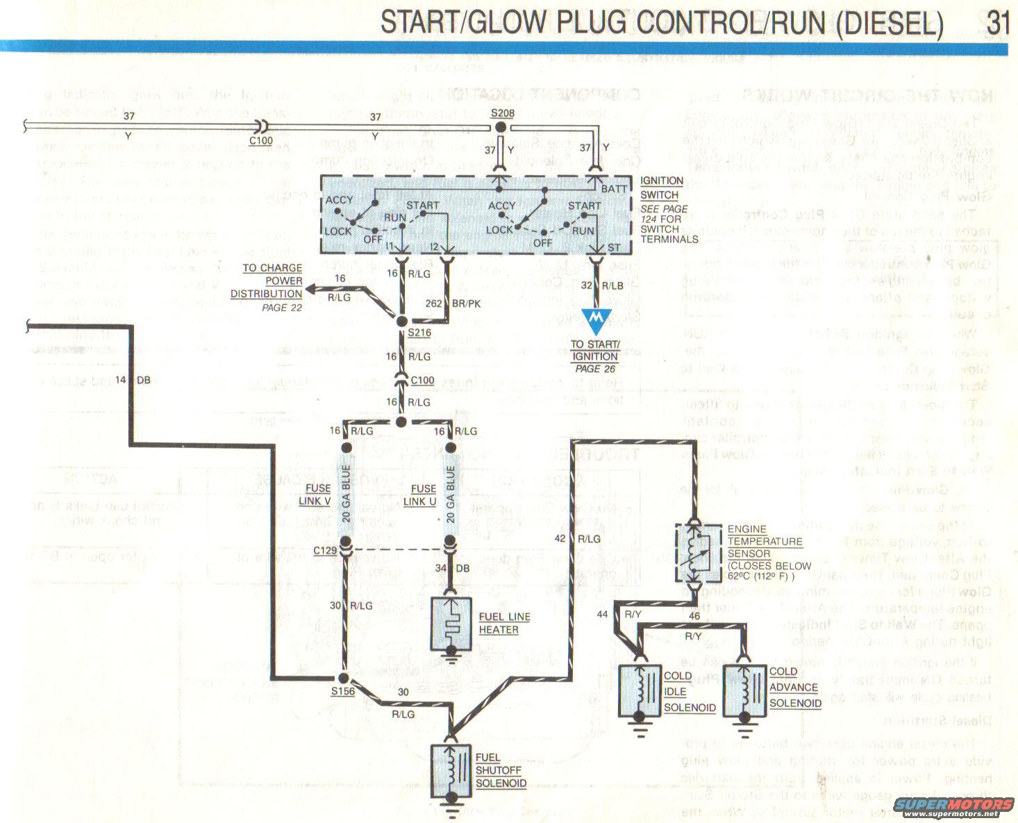
1988 Ford F-250 Diesel Start/Glow Plug Control Wiring Diagram - EVTM Page 31
Reference · 1987-1991 F-150All 8 wiring diagrams
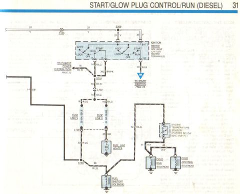
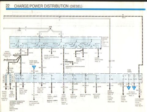
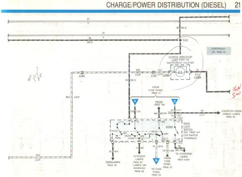
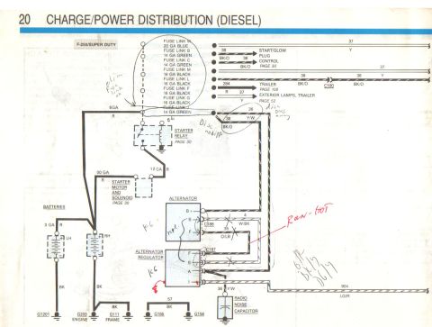
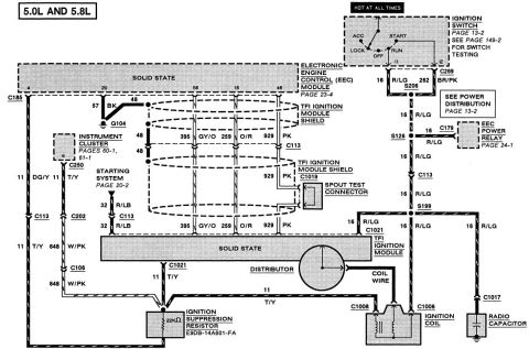
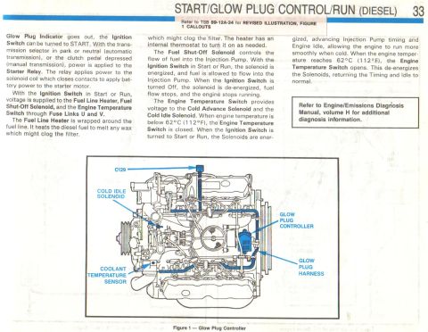
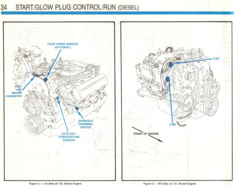
Start/glow plug run schematic showing ignition switch terminals, fuse links U and V, fuel line heater, fuel shutoff solenoid, cold idle/advance solenoids, and engine temperature sensor.
Part of 1987-1991 Ford F-150 Wiring Diagrams
This is page 31 of a Ford Electrical & Vacuum Troubleshooting Manual (EVTM) showing the Start/Glow Plug Control/Run circuit wiring diagram for a diesel engine. The diagram traces power from circuit 37 Y through splice S208 to the ignition switch (with ACCY, START, RUN, LOCK, OFF positions and BATT, I1, I2, ST terminals; the reader is referred to page 124 for switch terminal details). From terminal I1, circuit 16 R/LG feeds through splice S216 and connector C100 to fuse link V and fuse link U (both 20 GA blue). Circuit 262 BR/PK comes from terminal I2, and circuit 32 R/LB from terminal ST goes to the start/ignition circuit on page 26; a branch also goes to charge/power distribution on page 22. Downstream loads shown include the fuel line heater (circuits 34 DB, 30 R/LG through connector C129 and splice S156), the fuel shutoff solenoid (30 R/LG), and, via circuit 42 R/LG through the engine temperature sensor, which closes below 62°C (112°F), the cold idle solenoid and cold advance solenoid on circuits 44 R/Y and 46 R/Y. A reader can learn wire gauges, colors, circuit numbers, splice/connector IDs, and component interconnections for diesel start and glow plug operation.
Is this accurate? Sign in to help verify it.
Frequently asked questions
- What wire feeds the fuel shutoff solenoid on the diesel start/glow plug circuit?
- The fuel shutoff solenoid is fed by circuit 30 R/LG (red/light green) through splice S156.
- At what temperature does the engine temperature sensor close in this diesel circuit?
- The diagram states the engine temperature sensor closes below 62°C (112°F), which then powers the cold idle solenoid and cold advance solenoid via circuits 44 R/Y and 46 R/Y.
- What fuse links protect the glow plug/fuel line heater circuits?
- Fuse Link V and Fuse Link U, both 20 gauge blue fuse links, are in the 16 R/LG feed circuits.
- Where are the ignition switch terminal details found?
- The diagram notes 'See page 124 for switch terminals' for the ignition switch.
- What circuit goes from the ignition switch ST terminal?
- Circuit 32 R/LB (red/light blue) runs from the ST terminal to the Start/Ignition circuit on page 26.
No comments yet.