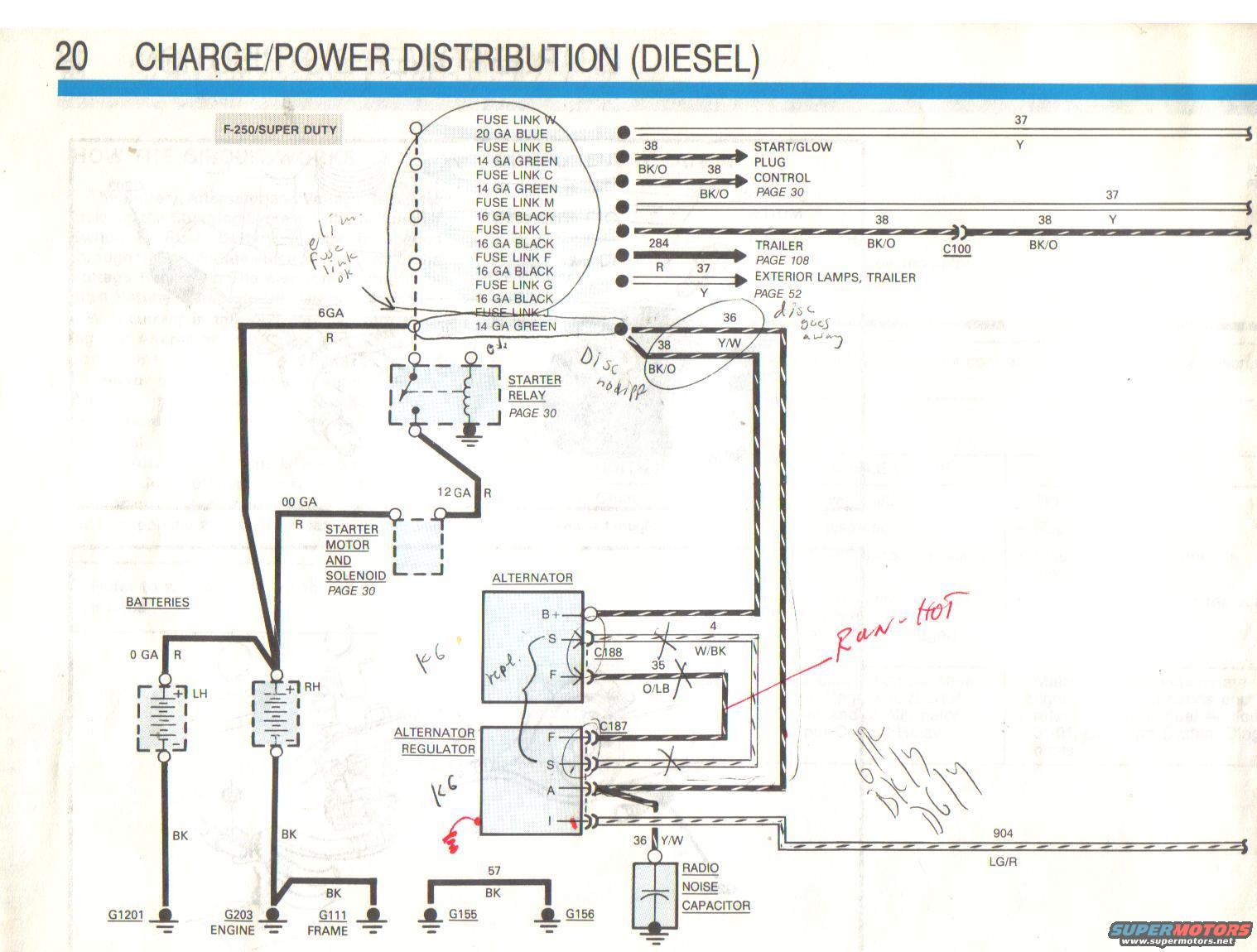
1988 Ford F-250 Diesel Charge/Power Distribution Wiring Diagram - EVTM Pg 20
Reference · 1987-1991 F-150All 8 wiring diagrams
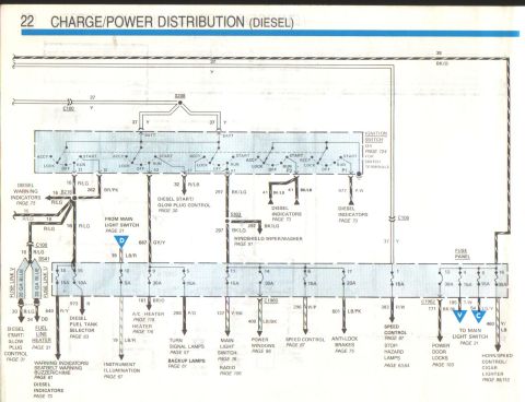
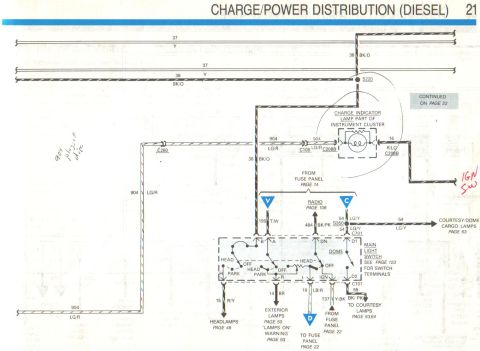
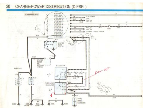
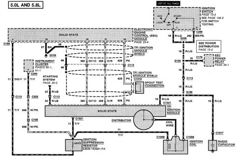
Diesel charge/power distribution schematic for an F-350/Super Duty showing battery, starter relay, starter solenoid, alternator/regulator, fuse links, and wire gauges/colors.
Part of 1987-1991 Ford F-150 Wiring Diagrams
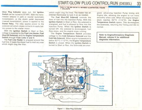
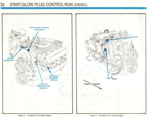
This is page 20 of a Ford Electrical & Vacuum Troubleshooting Manual (EVTM) showing the Charge/Power Distribution circuit for a diesel F-250/Super Duty. The diagram traces power from dual batteries (LH with 0 GA red positive cable, both with BK ground cables to grounds G1201, G203 engine, and G111 frame) through 00 GA and 12 GA red cables to the starter motor and solenoid and starter relay (detailed on page 30). A bank of fuse links (W 20 GA blue; B, C, J 14 GA green; M, L, F, G 16 GA black) feeds circuits 37 (Y), 38 (BK/O to start/glow plug control on page 30), 284 (trailer, page 108), and exterior lamps/trailer (page 52), passing through connector C100. The alternator (B+, S, F terminals, connector C188) connects via circuit 4 W/BK and circuit 35 O/LB to the external alternator regulator (F, S, A, I terminals, connector C187), with circuit 36 Y/W feeding a radio noise capacitor and circuit 904 LG/R exiting right. Handwritten owner notes indicate troubleshooting: a wire that "Ran HOT," fuse link elimination "ok," and component replacement marks. Useful for diagnosing charging system and power distribution problems on the diesel F-250/Super Duty.
Is this accurate? Sign in to help verify it.
Frequently asked questions
- What fuse links are used in the F-250 diesel charge/power distribution circuit?
- Fuse Link W (20 GA blue), Fuse Links B, C and J (14 GA green), and Fuse Links M, L, F and G (16 GA black).
- What wire connects the alternator to the alternator regulator?
- Circuit 4 (W/BK) from the S terminal and circuit 35 (O/LB) from the F terminal, through connectors C188 (alternator) and C187 (regulator).
- What gauge are the battery and starter cables on the diesel F-250?
- The LH battery positive cable is 0 GA red, the cable to the starter motor and solenoid is 00 GA red, and the starter relay feed is 12 GA red; ground cables are BK to grounds G1201, G203 (engine) and G111 (frame).
- Where does circuit 38 (BK/O) go?
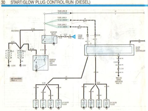
- Circuit 38 BK/O feeds the Start/Glow Plug Control (page 30) and also passes through connector C100; circuit 284 goes to the trailer circuit (page 108) and another branch goes to exterior lamps/trailer (page 52).
- What is the radio noise capacitor connected to?
- It is connected to circuit 36 (Y/W) coming from the alternator regulator I terminal and is grounded.


No comments yet.