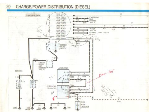
1988 Ford F-250 Diesel Start & Glow Plug Wiring Diagram - EVTM Page 30
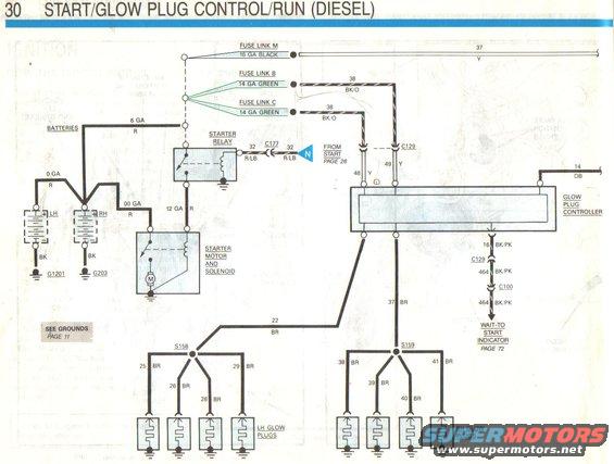
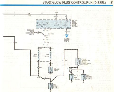
Start/glow plug control schematic showing batteries, starter relay/solenoid, glow plug controller, glow plugs, and the wait-to-start indicator circuit with wire gauges and colors.
Part of 1987-1991 Ford F-150 Wiring Diagrams
This is page 30 of a Ford Electrical & Vacuum Troubleshooting Manual (EVTM) wiring diagram titled "START/GLOW PLUG CONTROL/RUN (DIESEL)." It shows the starting and glow plug circuit for a diesel engine with dual batteries. Power flows from the LH and RH batteries (grounded at G1201 and G203 via black wires, connected with 6 GA, 0 GA, and 00 GA red cables) through fuse link M (16 GA black) and fuse links B and C (14 GA green) to circuits 37 (yellow) and 38 (black/orange). The starter relay receives circuit 32 (red/light blue) through connector C177 from the start circuit on page 26 and feeds the starter motor and solenoid via a 12 GA red wire. The glow plug controller receives circuits 48 and 49 (yellow, via C129) and circuit 14 (dark blue), and outputs circuit 16/464 (black/pink) through connectors C129 and C100 to the wait-to-start indicator (page 72). Glow plug feeds run via circuit 22 (brown) to splice S158, branching to circuits 25, 26, 28, and 29 (brown) for the LH glow plugs, and via circuit 37 (brown) to splice S159, branching to circuits 38, 39, 40, and 41 (brown) for the RH glow plugs. Cross-references point to grounds on page 11.
Is this accurate? Sign in to help verify it.
Frequently asked questions
- What wire feeds the starter relay from the ignition start circuit?
- Circuit 32, a red/light blue (R/LB) wire, comes from the start circuit on page 26 through connector C177 to the starter relay.
- What fuse links protect the glow plug circuit?
- Fuse Link M (16 GA black) feeds circuit 37 (yellow), while Fuse Links B and C (both 14 GA green) feed circuits 38 (black/orange) to the glow plug controller through connector C129.
- What wire colors go to the glow plugs?
- All glow plug wires are brown (BR): circuit 22 to splice S158 branching into circuits 25, 26, 28, 29 for the LH glow plugs, and circuit 37 to splice S159 branching into circuits 38, 39, 40, 41 for the RH glow plugs.
- Where are the batteries grounded?
- The LH battery grounds at G1201 and the RH battery grounds at G203, both via black (BK) wires. See grounds on page 11.
- How is the wait-to-start indicator connected?
- The glow plug controller sends circuit 16 (black/pink) through connector C129, becoming circuit 464 (BK/PK) through C100, to the wait-to-start indicator shown on page 72.
Comments
More from this build

No comments yet.