1968-1979 Chevy Corvette Spare Tire Carrier Exploded Parts Diagram
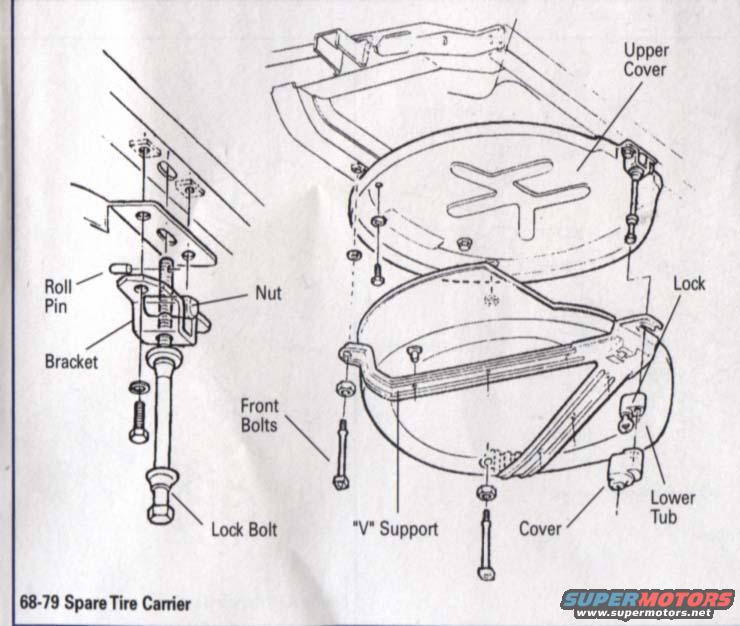
Exploded parts diagram of the 68-79 spare tire carrier showing bracket, lock bolt, V-support, covers and tub.
Part of 1968-1982 Chevrolet Corvette Exploded Parts Diagrams
This document is an exploded parts diagram of the spare tire carrier assembly for 1968-1979 vehicles (uploaded as applicable to a Chevrolet Corvette). The illustration shows how the underbody-mounted spare tire carrier is assembled, with callouts identifying each major component: the Upper Cover with its cross-shaped stamped reinforcement, the Lower Tub that holds the spare tire, the "V" Support frame that cradles the tub, the Cover, and the Lock mechanism at the rear. On the left side of the diagram, a detail view shows the release/mounting hardware: the Roll Pin, Nut, Bracket, and the long Lock Bolt that secures the carrier closed. Front Bolts are shown attaching the V-support to the underbody. Fastener locations (bolts, nuts, and washers) are illustrated in exploded fashion, showing their orientation and where they thread into the frame and carrier components. The diagram is captioned "68-79 Spare Tire Carrier." A reader can use this drawing to understand the order of assembly, identify part names when ordering replacements, and see how the lock bolt and bracket hardware release the lower tub to access the spare tire. No part numbers, torque specifications, or textual instructions appear in the document.
Is this accurate? Sign in to help verify it.
Frequently asked questions
- What years does this spare tire carrier diagram cover?
- The caption states it applies to 1968-1979 models ("68-79 Spare Tire Carrier").
- What parts make up the 68-79 spare tire carrier?
- The diagram labels the Upper Cover, Lower Tub, "V" Support, Cover, Lock, Bracket, Roll Pin, Nut, Lock Bolt, and Front Bolts.
- How is the spare tire carrier secured closed?
- A long Lock Bolt passes through a Bracket with a Roll Pin and Nut, shown in the detail view on the left of the diagram.
- Does this document include part numbers or torque specs?
- No. It is an exploded illustration with component name callouts only; no part numbers or torque values are shown.
Comments
More from this build

No comments yet.