Corvette Headlamp & Wiper Door Vacuum Hose Routing Diagram - C3 Vacuum System
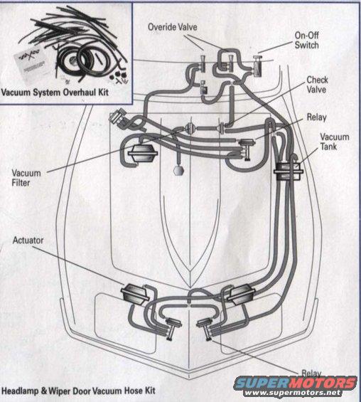
Headlamp & wiper door vacuum hose kit routing diagram showing override valve, on-off switch, check valve, relays, vacuum tank, vacuum filter, and actuators across the engine bay.
This document is an illustrated vacuum hose routing diagram for the headlamp and wiper door vacuum system, apparently from a parts catalog page advertising a 'Headlamp & Wiper Door Vacuum Hose Kit.' The main illustration shows a top-down view of the front end of a Corvette-style hood/front clip with the complete network of vacuum hoses drawn in place. Callout labels identify the major components in the system: the override valve, on-off switch, check valve, relays (one near the firewall and one near the headlamp area), vacuum tank, vacuum filter, and the headlamp actuators. An inset photo in the upper-left corner shows the contents of a 'Vacuum System Overhaul Kit,' which includes an assortment of pre-formed vacuum hoses, grommets/seals, small hardware, and what appears to be an instruction sheet. A reader can use this diagram to see how the vacuum hoses route between the tank, filter, valves, relays, and actuators for the hidden headlamps and wiper door, making it useful for diagnosing vacuum leaks or completely rebuilding the system with a replacement hose kit. The document itself carries no visible year, model, or part number text, though the body shape depicted is consistent with a C3 Corvette.
Is this accurate? Sign in to help verify it.
Frequently asked questions
- What components are shown in the headlamp and wiper door vacuum system diagram?
- The diagram labels an override valve, on-off switch, check valve, two relays, vacuum tank, vacuum filter, and headlamp actuators, all connected by routed vacuum hoses.
- What is included in the Vacuum System Overhaul Kit shown?
- The inset photo shows an assortment of vacuum hoses of various lengths and shapes, rubber seals/grommets, small hardware pieces, and an instruction/reference sheet.
- Where is the vacuum tank located in this system?
- Per the diagram, the vacuum tank is located on the passenger (right) side of the engine compartment near the firewall area, connected by hoses running toward the front of the car.
- How many relays are in the headlamp/wiper door vacuum system shown?
- Two relays are labeled: one near the firewall/upper area of the diagram and one down near the headlamp actuators at the front.
Comments
More from this build
No comments yet.