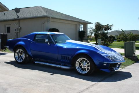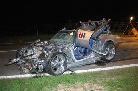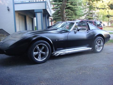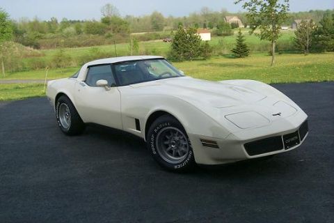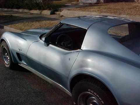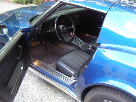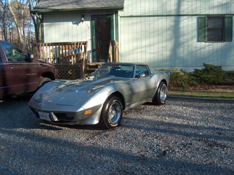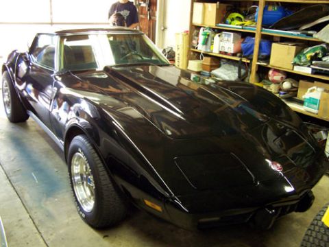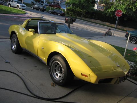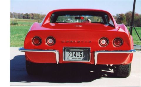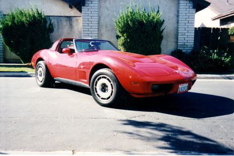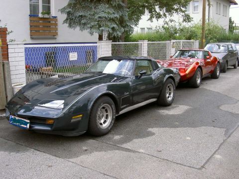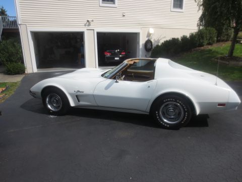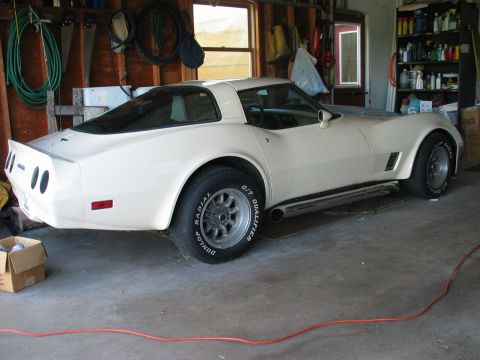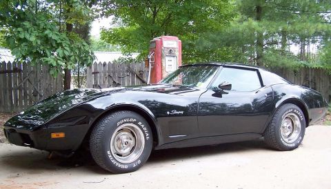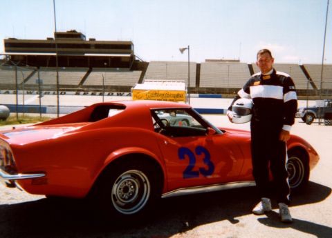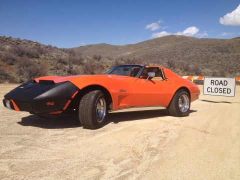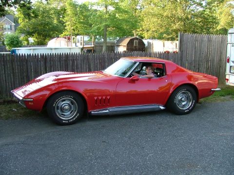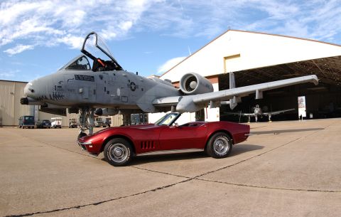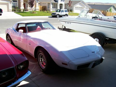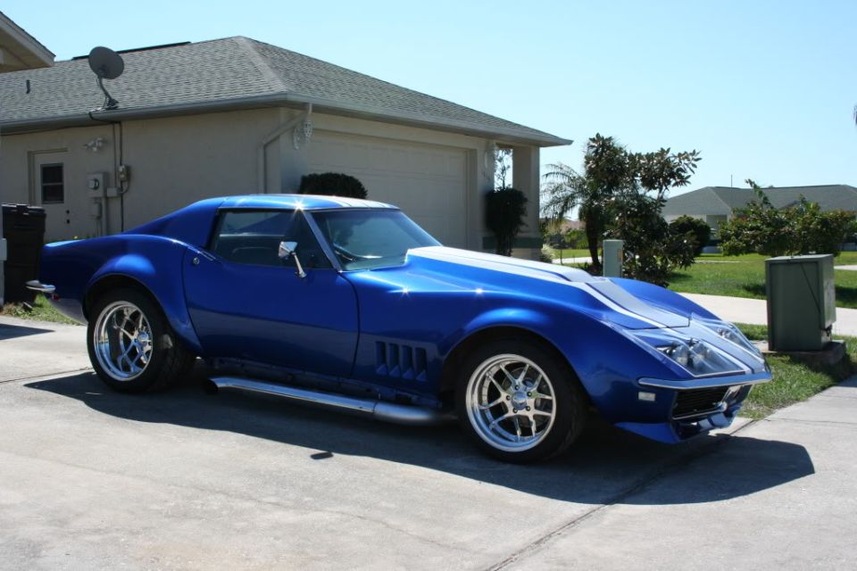
The 1968-1982 Chevrolet Corvette C3 is the longest-running Corvette generation, wearing production bodywork drawn from the Mako Shark II show car over a chassis carried forward from the 1963 C2. It opened at the top of the horsepower era, with the 435 hp L71 427 and the race-intent L88 and all-aluminum ZL1 big blocks, then rode the emissions decline down to a 165 hp (net) base 350 by 1975. Chrome bumpers gave way to body-color urethane in 1973-1974, a fastback glass rear window arrived in 1978, and the generation closed in 1982 with Cross-Fire throttle-body injection and the Collector Edition hatchback.
Other Chevrolet Corvette generations
Platform and body
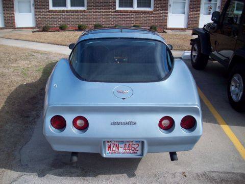
The 1968-1982 Corvette C3 kept the C2's ladder-type steel frame, 98 inch wheelbase, and independent rear suspension with a transverse leaf spring. The fiberglass body was new, shaped after the Mako Shark II concept. Coupes used removable T-top roof panels from 1968 on, and a convertible was offered through 1975. The 1973 model year brought a body-color urethane front bumper cover while the rear stayed chrome; 1974 added the urethane rear, ending chrome bumpers on the Corvette. In 1978 the tunneled rear window gave way to a large fastback glass backlight, and the 1982 Collector Edition made that glass a lifting hatch for the first time.
Engine lineup
Small blocks: the 327 carried over for 1968 (300 hp base, 350 hp L79), replaced by the 350 in 1969 (300 hp base, 350 hp L46). The solid-lifter LT-1 350 made 370 hp gross in 1970 and ran through 1972. Big blocks were 427s in 1968-1969 (L36 390 hp, L68 400 hp, tri-carb L71 435 hp with optional L89 aluminum heads, plus the underrated race-oriented L88 and the 1969-only all-aluminum ZL1), then 454s from 1970 (LS5 390 hp gross, dropping to 365 hp for 1971) with the LS6 454 rated 425 hp gross for 1971. Big blocks ended after 1974.
- 1972: GM switched from gross to net ratings, so numbers drop on paper. The base 350 read 200 hp net that year; compare pre-1972 and post-1972 figures with that change in mind.
- 1975: base L48 350 bottomed out at 165 hp net; the optional L82 made 205 hp. Catalytic converters and HEI ignition arrived this year.
- 1978: L48 at 185 hp, L82 up to 220 hp net.
- 1980: California cars got a 305 with automatic only; 49-state cars kept the 350.
- 1981: one engine only, the L81 350 at 190 hp, with Computer Command Control.
- 1982: L83 350 with Cross-Fire twin throttle-body injection, 200 hp, automatic only.
Drivetrain and transmissions
All C3s are front engine, rear drive, with the differential mounted to the frame and halfshafts acting as suspension links. Manuals were Muncie four-speeds until the Borg-Warner Super T-10 phased in during 1974, in wide and close ratio versions either way. The only automatic from 1968 through 1975 was the three-speed Turbo Hydra-Matic 400, which had replaced the C2's two-speed Powerglide for 1968. The lighter THM 350 arrived behind the base L48 in 1976 (the L82 kept the THM 400 through 1977) and was the sole automatic from 1978 through 1981. For 1982 the new four-speed 700-R4 overdrive automatic was the only transmission; no manual was offered that year.
Year-by-year notes
- 1968: new body, T-tops, 327 and 427 engines, no Stingray badging this one year.
- 1969: Stingray name returns as one word, 350 replaces the 327 (with the 350 hp L46 option), ZL1 aluminum 427 offered at a price that roughly doubled the car's cost, so only a couple were sold.
- 1970: LT-1 370 hp 350 and LS5 454 debut; fender flares and egg-crate side vents.
- 1971: compression drops across the board for low-lead fuel; LS6 454 at 425 hp gross is the last big-power option.
- 1972: net horsepower ratings begin; last year for the LT-1 and for chrome front bumpers.
- 1973: urethane nose, chrome rear bumper, one-year-only combination.
- 1974: urethane rear bumper in two pieces; last big block (LS4 454) and last true dual exhaust.
- 1975: catalytic converter, base 165 hp, last C3 convertible.
- 1977: Stingray script dropped; console and interior updates.
- 1978: fastback glass rear window, 25th Anniversary two-tone paint option, and the black and silver Indy 500 Pace Car replica.
- 1980: integrated front and rear spoilers, weight reduction, 85 mph speedometer.
- 1981: production moved from St. Louis to Bowling Green, Kentucky during the model year; fiberglass rear leaf spring on some cars.
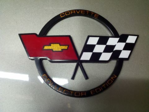
- 1982: Cross-Fire injection, 700-R4 automatic only, Collector Edition with hatch glass, turbine-style wheels, and silver-beige paint.
Trims and variants
The C3 used option codes rather than trim lines. The ones that matter to buyers: L88 and ZL1 427 race packages (1968-1969), LT-1 solid-lifter 350 (1970-1972), the ZR1 competition package built around the LT-1 (1970-1972), the 1971-only ZR2 built around the LS6 454 (12 cars), the LS5 and LS6 454s, the 1978 Pace Car replica and Silver Anniversary paint, and the 1982 Collector Edition. Gymkhana suspension (FE7) was a common handling option from mid-decade on. Early chrome-bumper cars (1968-1972) trade at a premium over the later rubber-bumper cars, with 1968-1971 big blocks at the top.
Asked all the time
What engines came in the 1968-1982 Corvette C3?
The Corvette C3 launched in 1968 with 327 small blocks (300 and 350 hp) and 427 big blocks up to the 435 hp L71, plus the race-oriented L88. The 350 replaced the 327 in 1969, 454s replaced the 427 in 1970 (LS5, then the 425 hp gross LS6 in 1971), and big blocks ended after 1974. From 1975 the C3 was 350-only except for a California 305 in 1980, finishing with the 200 hp Cross-Fire injected L83 350 in 1982.
Which years of the C3 Corvette are most desirable?
The 1968-1972 chrome-bumper Corvette C3s carry the strongest values, especially 1968-1971 big-block cars (L71, L88, LS6) and the 1970-1972 LT-1 350 small blocks. Among later cars, the 1975 convertible (last of the generation), the 1978 Pace Car replica, and the 1982 Collector Edition draw the most interest.
Why did C3 Corvette horsepower drop so much in the 1970s?
Two things hit the 1968-1982 Corvette C3. In 1972 GM switched from gross to net horsepower ratings, which lowered numbers on paper without changing the hardware much. Then real losses followed from compression drops for low-lead fuel (1971) and emissions equipment, including catalytic converters in 1975, when the base 350 bottomed at 165 hp net.
When did the C3 Corvette switch from chrome to rubber bumpers?
The Corvette C3 got a body-color urethane front bumper cover in 1973 while keeping the chrome rear bumper, making 1973 a one-year combination. The urethane rear followed in 1974. Cars from 1968-1972 are the chrome-bumper C3s.
What was special about the 1982 Corvette Collector Edition?
The 1982 Corvette Collector Edition was the C3's send-off: silver-beige paint, turbine-style aluminum wheels, and the first opening rear hatch glass on a Corvette. Like all 1982 C3s it used the 200 hp L83 350 with Cross-Fire throttle-body injection and the four-speed 700-R4 automatic; no manual was offered that year.
What transmissions did the C3 Corvette use?
The 1968-1982 Corvette C3 offered Muncie four-speed manuals until the Borg-Warner Super T-10 phased in during 1974, in wide and close ratio versions. The only automatic from 1968 to 1975 was the three-speed Turbo Hydra-Matic 400; the THM 350 joined it behind the base engine in 1976 and was the sole automatic from 1978 through 1981. The four-speed overdrive 700-R4 was the only transmission offered for 1982.
Technical Reference
Member-uploaded diagrams & documents for this generation. AI-classified; community-verified where badged.
Schematics (4)
- Driveshaft U-Joint Angle Alignment Diagram - Pinion Angle & Vibration GuideThis is a graphical reference diagram (credited to HOTRODDERS.COM) illustrating four possible driveline/driveshaft alignment geometries between two U-joint yokes and the resulting strain and vibration for each. Four…
- Driveshaft U-Joint Angle Diagram - Compensating vs Broken Back W ConfigurationThis document is a technical schematic illustrating two common driveshaft universal joint (U-joint) working-angle configurations. The top panel, labeled "Compensating Angles," shows a driveshaft with one U-joint angled…
- Pinion Angle Setting Chart - 4-Link & Ladder-Bar Driveline Angle DiagramThis document is an illustrated reference chart for setting driveline pinion angle. At the top, two drawings show where to place a protractor (angle finder): on the transmission tailshaft seal to measure the…
- Drum Brake Diagram - Wheel Cylinder, Brake Shoes & Star Adjusting ScrewThis document is a labeled schematic illustration of a drum brake assembly, uploaded to the gallery of a 1977 Chevrolet Corvette. The drawing shows a rear view of the complete drum brake with the drum removed, exposing…
Blueprints (9)
- Wheel Offset & Backspacing Diagram - Rim Width, Bolt Circle & Fitment TermsThis document is a labeled cross-section diagram of an automotive wheel and tire assembly, illustrating the key dimensional terms used when measuring and fitting wheels. The drawing shows a wheel/tire in side…
- Wheel Offset & Backspacing Diagram - Rim Width, Bolt Circle & Fitment TermsThis document is a technical cross-section diagram of a wheel and tire assembly mounted at a fender, used as a reference for understanding wheel fitment terminology. It labels and dimensions the key measurements…
- Tire Cross-Section Diagram: Tread Width vs Rim Width vs Section WidthThis document is a simple cross-section diagram of a tire mounted on a wheel rim, illustrating three key tire and wheel measurements. The illustration shows a tire in cross-section (cut view) seated on a rim, with…
- Wheel Cross-Section Diagram - Offset, Back Spacing, Rim Width TerminologyThis document is a labeled cross-section diagram of an automotive wheel, illustrating standard wheel measurement terminology. The diagram shows a wheel in profile (cut-away) view with dimension lines and callouts…
- Wheel Offset & Backspacing Diagram - Rim Width, Offset (C) & Back-Space (B)This document is a labeled cross-section diagram explaining how to measure key wheel (rim) dimensions. The drawing shows a wheel in cross-section viewed from the back side, with red dimension arrows overlaid. The full…
- Wheel Offset, Backspace & Bolt Circle Diagram - Wheel Measurement GuideThis document is a labeled cross-section diagram of an automotive wheel (rim), illustrating the standard dimensional terminology used when measuring or selecting wheels. The drawing shows a wheel in section view with…
- Wheel Offset & Backspacing Diagram - Centerline and Hub Mounting Surface ExplainedThis document is a labeled cross-section diagram of an automotive wheel, illustrating the key dimensional reference points used to describe wheel fitment. The diagram shows a wheel rim in profile (cut vertically…
- Wheel Offset Measurement Diagram - Rim Width, Centerline & Mounting FaceThis document is a small technical diagram illustrating how wheel offset is measured on an automotive wheel. It shows a cross-section (profile) view of a wheel rim. Across the top, the overall "WIDTH" of the wheel is…
- Wheel Offset Diagram Explained - Positive, Zero & Negative Offset Cross-SectionsThis is a small illustrated reference diagram explaining wheel offset. It shows three cross-section drawings of wheels side by side, each with a vertical red line marked 'Wheel Center' indicating the wheel's…
Torque Specs (1)
- Standard & Metric Bolt Torque Specifications Chart – SAE Grade & Fastener MarkingsThis document is a general-purpose bolt torque specification chart titled "Standard Torque Specifications and Fastener Markings," commonly included in automotive repair manuals. It provides maximum safe torque values…
Exploded Parts (34)
- 1969-81 Chevrolet Corvette Engine Components Exploded View Diagram (Part 2)This is a scanned page from an automotive service/reference manual showing an exploded view of engine components, captioned 'Fig. 33 Exploded view of engine components (part 2)—1969–81 vehicles.' The illustration…
- Corvette Front Spindle & Wheel Bearings Exploded Diagram - Hub Assembly OrderThis document is a labeled exploded-view line drawing titled "Front Spindle & Wheel Bearings," showing the front hub/spindle assembly of a vehicle with front disc brakes. The illustration depicts the steering knuckle…
- 1969-81 Chevrolet Corvette V8 Engine Exploded View Diagram - Components Part 1This is a scanned page from an automotive repair manual showing Figure 31, an exploded view of engine components (part 1) applicable to 1969–81 vehicles. The illustration depicts a Chevrolet-style small-block V8 top…
- Corvette Air Injection Reactor (A.I.R.) System Diagram - Smog Pump & PartsThis document is an exploded parts diagram of the Air Injection Reactor (A.I.R.) system, apparently from a Corvette parts/reference catalog. It shows the emissions air-injection components mounted on a V8 engine and…
- 1978-1982 Chevrolet Corvette Glove Box Exploded Parts DiagramThis document is an exploded parts diagram labeled "78-82 Glove Box," illustrating the glove box assembly as installed in the passenger side of the dashboard. The line drawing shows the dash area with the glove box…
- 1968-79 Chevy Corvette Heater Box Exploded Diagram - Core, Inner/Outer BoxThis document is a scanned exploded parts diagram labeled "68-79 Heater Box," showing the heater box assembly for 1968–1979 Chevrolet Corvette models. The line drawing depicts the heater assembly in exploded view with…
- 1977-82 Corvette 350 A/C Compressor Mounting Exploded Diagram (AH-314–AH-318)This document is an exploded parts diagram showing the air conditioning compressor mounting arrangement for 1977-1982 Chevrolet Corvettes equipped with the 350 engine, as stated in its caption "77-82 Compressor…
- 1976-77 Chevy Corvette Radio & Dash Components Exploded Parts DiagramThis document is an exploded parts diagram (Fig. 6) showing the radio and related instrument panel components for 1976–77 vehicles, uploaded to a 1977 Chevrolet Corvette gallery. The illustration depicts the…
- 1975-79 Corvette Bumper Covers & Retainers Exploded Diagram - ZBU-389, SRB-077This scanned catalog/reference page shows exploded parts diagrams for 1975-1979 Chevrolet Corvette bumper covers and their retainers. The top-left panel pictures a single Bumper Cover Retainer with part number ZBU-389…
- 1973-77 Corvette Rear Window Frame Exploded View & Storage Tray Bracket I-1209This scanned page from an automotive parts reference shows two related items for 1973-1977 Chevrolet Corvette rear window hardware. On the left, a photograph shows a black metal 'Rear Window Storage Tray Handle &…
- 1972-82 Chevy Corvette 350 Alternator Mounting Diagram - Bracket & Bolt LayoutThis document is an exploded parts diagram showing the alternator mounting arrangement for 1972–1982 Chevrolet models equipped with the 350 engine, as stated in the caption "72-82 350 Alternator Mounting." The line-art…
- 1971-1982 Chevrolet Corvette Fuel Door Exploded Parts DiagramThis document is a scanned exploded parts diagram labeled "71-82 Fuel Door," showing the components of the fuel filler door assembly used on 1971-1982 Chevrolet Corvettes. The illustration depicts how the assembly…
- 1968-82 Corvette Wiper System Exploded Diagram - Motor, Arms & LinkageThis document is an exploded parts diagram of the windshield wiper system for 1968–1982 model years, titled "68-82 Wiper System." It was uploaded to the gallery of a 1977 Chevrolet Corvette, which falls within the…
- 1968-82 Chevrolet Corvette Windshield Moldings Diagram - Trim IdentificationThis document is a labeled line-art diagram from an automotive reference showing the windshield moldings on 1968–1982 Chevrolet Corvettes. The illustration presents a front view of the car with the windshield frame and…
- 1968-82 Chevy Corvette Inner Skirt Diagram - Skirt Seals & A-Arm Dust ShieldThis document is a black-and-white exploded parts diagram labeled "68-82 Inner Skirt," showing the inner fender skirt assembly for 1968-1982 Chevrolet Corvettes. The illustration depicts the inner skirt panel (inner…
- 1968-82 Corvette Headlight Components Exploded Diagram - Actuator & LinkageThis document is an exploded parts diagram titled "68-82 Headlight Components," covering the hidden (pop-up) headlight system used on 1968–1982 Chevrolet Corvettes. The illustration shows how the headlight assembly…
- 1968-79 Corvette Transmission Mount Exploded Diagram - Bracket & Bolt KitThis document is an exploded parts diagram illustrating the transmission mount assembly for 1968-79 vehicles (uploaded as applicable to a 1977 Chevrolet Corvette). The line drawing shows how the transmission mount…
- 1968-1979 Chevy Corvette Spare Tire Carrier Exploded Parts DiagramThis document is an exploded parts diagram of the spare tire carrier assembly for 1968-1979 vehicles (uploaded as applicable to a Chevrolet Corvette). The illustration shows how the underbody-mounted spare tire carrier…
- 1968-79 Corvette Rear Storage Compartment Exploded Parts DiagramThis document is an exploded parts diagram of the rear storage compartment for 1968–1979 Chevrolet Corvettes, as captioned "68-79 Rear Storage Compartment." The illustration shows the compartment assembly disassembled…
- 1968-79 Corvette Splash Shield Diagram - Mounting & Fastener LocationsThis document is a single page from a Chevrolet Corvette parts reference showing exploded line-art of splash shield components. The page carries two captions: a header reading "63-67 Outer Splash Shield" (referring to…
- 68-77 Corvette A/C Heater Box & Duct Exploded Diagram (Plus 79-82 Ducts)This scanned page contains three exploded parts diagrams for Chevrolet Corvette heating and air conditioning ductwork. The upper-left diagram, labeled "68-77 Lower Outlet," shows the exploded assembly of a lower air…
- 1968-1977 Chevy Corvette Heater Box Seal Exploded Parts DiagramThis document is a scanned exploded-view parts illustration labeled "68-77 Heater Box Seal," covering the heater box assembly used on 1968–1977 Chevrolet Corvettes. The line drawing shows the complete heater box and…
- 1965-1982 Chevy Corvette Rear Wheel Bearing Assembly Exploded DiagramThis document is an exploded parts diagram of the rear wheel bearing assembly for 1965-1982 Chevrolet Corvettes, as stated in its caption '65-82 Rear Wheel Bearing Assembly.' The illustration shows how the rear hub and…
- 1964-81 Chevy Corvette Clutch Linkage Exploded Parts DiagramThis document is an exploded parts diagram titled "64-81 Clutch Linkage," showing the complete mechanical clutch linkage assembly for 1964–1981 Chevrolet Corvette models. The illustration identifies every component in…
- 1963-82 Corvette Rear Suspension Exploded Diagrams - Spring, Strut Rod, Sway BarThis document is a single page of exploded parts diagrams covering the rear suspension of 1963–1982 Chevrolet Corvettes. It contains three labeled line drawings. The first, titled "63-82 Rear Spring," shows the…
- 1963-82 Chevrolet Corvette Power Steering Linkage Exploded DiagramThis document is a labeled exploded-view line drawing of the power steering linkage used on 1963–1982 Chevrolet Corvettes, as indicated by its caption "63-82 Power Steering Linkage." The illustration shows the complete…
- 1963-82 Chevy Corvette Control Arm Mounting Diagram - Upper & Lower A-ArmThis document is a labeled exploded-view diagram titled "63-82 Control Arm Mounting," covering the front control arm mounting arrangement for 1963–1982 Chevrolet Corvettes. The line drawing shows the upper A-arm and…
- 1963-82 Chevrolet Corvette Chassis Components Diagram - Frame & Body MountsThis document is an exploded isometric line drawing titled "63-82 Chassis Components," covering the full frame assembly for 1963–1982 Chevrolet Corvette models. The main illustration shows the complete perimeter frame…
- 1963-82 Corvette 327 & 350 Power Steering Pump Exploded DiagramThis document is an exploded parts diagram showing the power steering pump assembly for 1963–1982 Chevrolet Corvettes equipped with 327 and 350 cubic inch engines. The illustration depicts the components in exploded…
- GM 8.1L EVAP System Hose Routing Diagram - Canister, Tank & Vent LinesThis document is an unlabeled line-art routing diagram of an evaporative emission (EVAP) system, filed by the uploader as the '8.1L EVAP route.' It contains no written legend or text other than ten numbered callouts…
- GM 8.1L EVAP System Hose Routing Diagram - Canister, Tank & Vent LinesThis document is an untitled, unlabeled routing schematic identified by its upload filename as an 8.1L EVAP (evaporative emissions) hose routing diagram. The drawing contains no written text other than numeric callouts…
- 1968-77 Chevrolet Corvette Carpet Set Diagram - Piece LayoutThis document is a scanned illustration showing the layout of a multi-piece carpet set for a 1968-1977 Chevrolet Corvette (as indicated by the '68-77' label printed in the lower left corner and the upload title '68-77…
- 1968-82 Chevrolet Corvette Coupe Weatherstrip Diagram - T-Top & Door SealsThis document is a line-art illustration showing the weatherstrip locations on a 1968–1982 Corvette coupe body. The drawing depicts the front three-quarter view of the coupe with the weatherstrip channels rendered in…
- 1968-82 Corvette Firewall Insulation Panel Diagram (C3)This document is a scanned catalog-style illustration titled "68-82 Firewall Insulation." It shows a single line drawing of the firewall insulation panel used on 1968–1982 model vehicles (filed by the uploader under a…
Vacuum Routing (1)
- Corvette Headlamp & Wiper Door Vacuum Hose Routing Diagram - C3 Vacuum SystemThis document is an illustrated vacuum hose routing diagram for the headlamp and wiper door vacuum system, apparently from a parts catalog page advertising a 'Headlamp & Wiper Door Vacuum Hose Kit.' The main…
Data/Spec Plates (1)
- Standard & Metric Conversion Factors Chart - Torque, Pressure, Volume, MPGThis document is a standard-to-metric conversion factors chart, typical of the reference pages found in automotive repair manuals. It is organized into sections covering Length–Distance (inches to millimeters, feet to…
Service Procedures (1)
- Common Tire Wear Patterns & Causes Chart - Diagnosis and CorrectionsThis document is a scanned reference chart titled "Common tire wear patterns and causes." It is organized as a table with three rows — Condition, Effect (shown via illustrations), Cause, and Correction — across seven…
The wall · registered 1968–1982 Corvettes
Sorted by depth of documentation. Click any vehicle to open its permanent record.