Home/
Registry/
Chevrolet/
Corvette/
1968-1982/
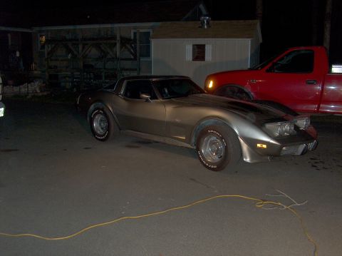
“Other vette pictures”/
Photo
supermotors.net/registry/media/993157
Wheel Offset & Backspacing Diagram - Rim Width, Bolt Circle & Fitment Terms
.gif)
Dimensioned engineering cross-section of a wheel and tire labeling section width, rim width, bolt circle, pilot diameter, offset and static radius.
This document is a labeled cross-section diagram of an automotive wheel and tire assembly, illustrating the key dimensional terms used when measuring and fitting wheels. The drawing shows a wheel/tire in side cross-section with callouts identifying: section width and tire width (measured across the tire), fender lip location, overall rim width and rim width (measured across the wheel), caliper height clearance, a dimension of .920, section height (tire sidewall), backspace dimension (from mounting face to inner rim edge), nominal wheel diameter, bolt circle diameter, pilot diameter (the center bore that locates on the hub), positive offset (distance from the wheel centerline to the mounting surface), and static radius (from axle centerline to the ground). A centerline symbol marks the axle center. The diagram contains no text describing a specific vehicle make, model, or year — it is a generic reference for understanding wheel fitment terminology such as backspacing, offset, bolt pattern, and clearance dimensions. A reader can learn how each of these wheel-fitment measurements relates to the others on an actual wheel cross-section, which is useful when selecting aftermarket wheels or verifying clearance to brake calipers and fenders.
Is this accurate? Sign in to help verify it.
Frequently asked questions
- What is positive offset on this diagram?
- The diagram labels OFFSET (POSITIVE) as the horizontal distance between the wheel's centerline and the wheel mounting surface, with the mounting surface positioned toward the outside of the wheel.
- What is the backspace dimension?
- The BACKSPACE DIMENSION is shown as the distance from the wheel's mounting face to the inboard edge of the rim.
- What wheel diameter measurements are shown?
- The diagram identifies NOMINAL WHEEL DIAMETER, OVERALL RIM WIDTH, RIM WIDTH, BOLT CIRCLE DIAMETER, and PILOT DIAMETER.
- How is static radius defined in this diagram?
- STATIC RADIUS is shown as the vertical distance from the wheel/axle centerline (℄) down to the bottom of the tire (ground contact).
- What tire measurements are labeled?
- The diagram labels SECTION WIDTH, TIRE WIDTH, and SECTION HEIGHT of the tire, plus the FENDER LIP location for clearance reference.
Comments
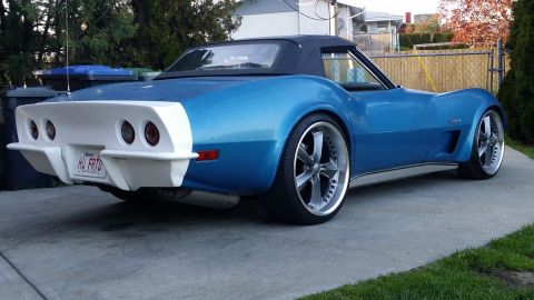
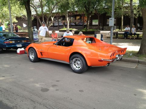
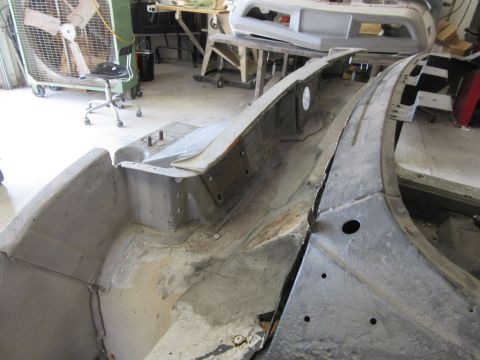
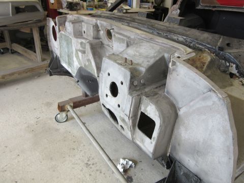
More from this build
No comments yet.