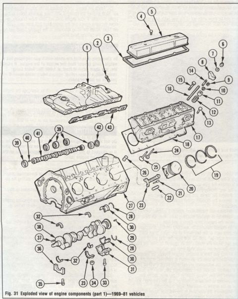
1969-81 Chevrolet Corvette Engine Components Exploded View Diagram (Part 2)
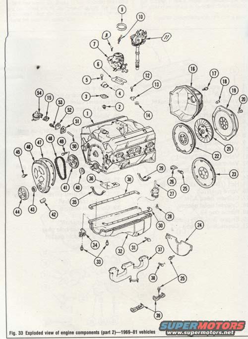
Exploded parts diagram (Fig. 33, part 2) of 1969-81 engine components with numbered callouts for block, pan, flywheel and timing parts.
This is a scanned page from an automotive service/reference manual showing an exploded view of engine components, captioned 'Fig. 33 Exploded view of engine components (part 2)—1969–81 vehicles.' The illustration depicts a V8 engine block disassembled into its major components, with numbered callouts (roughly 1 through 54) pointing to individual parts. Identifiable items in the drawing include the engine block, cylinder heads, intake manifold, carburetor, distributor, distributor cap, timing cover, timing chain and sprockets, harmonic balancer, flywheel/flexplate, clutch pressure plate and disc, bellhousing, oil pan and gaskets, oil pump, dipstick, exhaust manifolds, valve covers, and various brackets and fasteners. No parts legend or key matching the callout numbers is legible on this page; the numbered legend presumably appears elsewhere in the manual. Marginal text from adjacent columns is cropped and unreadable. The document explicitly states applicability to 1969–81 vehicles, which is consistent with the uploader's 1977 Chevrolet Corvette. A reader can use this figure to understand how the engine's major components fit together and their disassembly/assembly relationships, though part names for each number cannot be determined from this page alone.
Is this accurate? Sign in to help verify it.
Frequently asked questions
- What years does this engine components diagram cover?
- The caption states it applies to 1969–81 vehicles.
- Does this page include a legend identifying each numbered part?
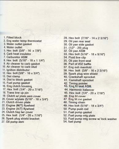
- No. The exploded view shows numbered callouts (approximately 1–54), but no legible legend or parts list appears on this page.
- What does the diagram show?
- An exploded view of engine components (labeled part 2 of a series), including the engine block, carburetor, distributor, timing cover and chain, flywheel/clutch components, bellhousing, oil pan, and exhaust manifolds, each identified by callout numbers.
- Is this part 1 or part 2 of the exploded engine view?
- The caption reads 'Fig. 33 Exploded view of engine components (part 2)', so it is part 2, despite the upload filename saying part 1.
Comments
More from this build
No comments yet.