Corvette Front Spindle & Wheel Bearings Exploded Diagram - Hub Assembly Order
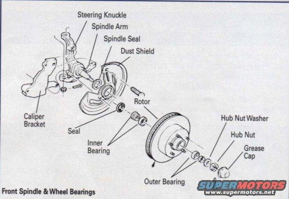
Exploded parts diagram of the front spindle and wheel bearings showing knuckle, rotor, inner and outer bearings, hub nut and grease cap.
This document is a labeled exploded-view line drawing titled "Front Spindle & Wheel Bearings," showing the front hub/spindle assembly of a vehicle with front disc brakes. The illustration depicts the steering knuckle with its integral spindle arm, followed outward along the spindle by the spindle seal, dust shield, inner seal, inner bearing, the brake rotor with wheel studs, the outer bearing, hub nut washer, hub nut, cotter pin, and grease cap. A caliper bracket is shown mounted adjacent to the knuckle. Each component is called out with a leader line to its position in the assembly, so a reader can learn the correct order in which parts stack onto the spindle when servicing or repacking front wheel bearings or replacing the rotor. The drawing contains no part numbers, torque specifications, year/model designations, or written procedures — it is purely an identification and assembly-sequence diagram. It was uploaded to a 1977 Chevrolet Corvette gallery alongside other C2/C3 Corvette reference diagrams, and nothing in the image contradicts that application, though the document itself states no applicability.
Is this accurate? Sign in to help verify it.
Frequently asked questions
- What is the order of parts on the front spindle?
- Per the diagram: spindle seal and dust shield at the knuckle, then the seal and inner bearing, the rotor, outer bearing, hub nut washer, hub nut, and finally the grease cap.
- Which bearing goes on the inboard side of the rotor?
- The inner bearing sits behind the rotor (with a seal), while the outer bearing goes on the outboard side, retained by the hub nut washer and hub nut.
- What holds the hub nut components in place at the end of the spindle?
- The hub nut is secured with the hub nut washer, and a cotter pin (shown near the grease cap) is depicted; the grease cap covers the assembly.
- Where does the caliper bracket mount?
- The caliper bracket is shown attaching adjacent to the steering knuckle, inboard of the dust shield and rotor.
Comments
More from this build
No comments yet.