Home/
Registry/
Ford/
Bronco/
1978-1979/
“buyers guide”/
Photo
supermotors.net/registry/media/756764
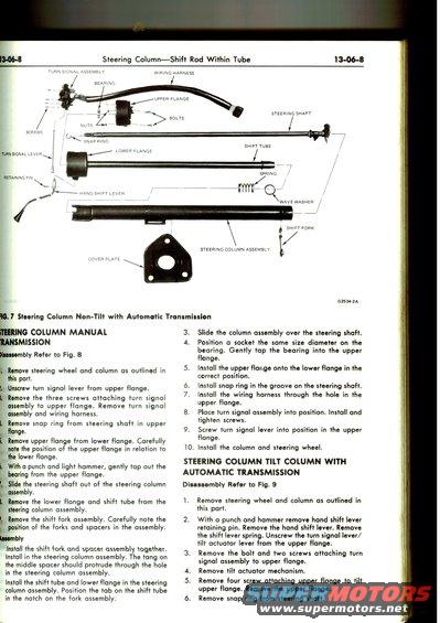
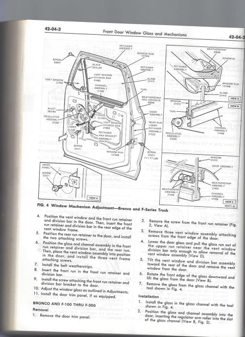
Diagram illustrates steering column components and assembly steps for non-tilt and tilt columns.
-8 Steering ColumnShift Rod Within Tube 'I 3-06-8 TURN SIGNAL ASSEMBLY BEARING I SCREWS , W, . [r w! SNAPRING I ' I I LOWER FLAN ITUHN SIGNAL LEVER I I / GE I . RETAINING PIN ;)\_ HAND SHIFT LEVER RING COLUMN MANUAL U NSMISSION ,: ssembly Refer to Fig. 8 Remove steering wheel and column as outlined in ; this part. Unscrew turn signal lever from upper flange. Remove the three screws attaching turn signal assembly to upper flange. Remove turn signal assembly and wiring harness. Remove snap ring from steering shaft in upper flange. Remove upper flange from lower flange. Carefully note the position of the upper flange in relation to the lower flange. With a punch and light hammer, gently top out the hearing from the upper flange. Slide the steering shaft out of the steering column 7} assembly. I Remove the lower flange and shift tube from the steering column assembly. Remove the shift fork assembly. Carefully note the " position of the forks and spacers in the assembly. " mbly I Install the shift fork and spaces assembly together. Install in the steering column assembly. The tang on the middle spacer should protrude through the hole In the steering column assembly. Install the shift tube and lower flange in the steering column assembly. Position the tab on the shift tube in the notch on the fork assembly. WIRING HARNESS 9. STEERING SHAFT SHIFT TUBE I - I SPRING 7 / , , m LQJ _ ._.__J ' SHIFT FORK 62534-2A . 7 Steering Column Non-Tilt with Automatic Transmission Slide the column assembly over the steering shaft. Position a socket the same size diameter on the bearing. Gently tap the bearing into the upper flange. Install the upper flange onto the lower flange in the correct position. Install snap ring in the groove on the steering shaft. Install the wiring harness through the hole in the upper flange. Place turn signal assembly into position. Install and tighten screws. Screw turn signal lever into position in the upper flange. l0. Install the column and steering wheel. STEERING COLUMN TILT COLUMN WITH AUTOMATIC TRANSMISSION Disassembly Refer to Fig. 9 I. 2. 5 Remove steering wheel and column as outlined in this part. With a punch and hammer remove hand shift lever retaining pin. Remove the hand shift lever. Remove the shift lever spring. Unscrew the turn signal lever/ tilt actuator lever from the upper flange. Remove the bolt and two screws attaching turn signal assembly to upper flange. Remove tilt actuator mechanism. Remove four screw attaching upper flange to tilt upper flange. Remove the upper flange. Remove snap ring from steering shaft.
Comments
More from this build

No comments yet.