Home/
Registry/
Ford/
Bronco/
1978-1979/
“buyers guide”/
Photo
supermotors.net/registry/media/1109831
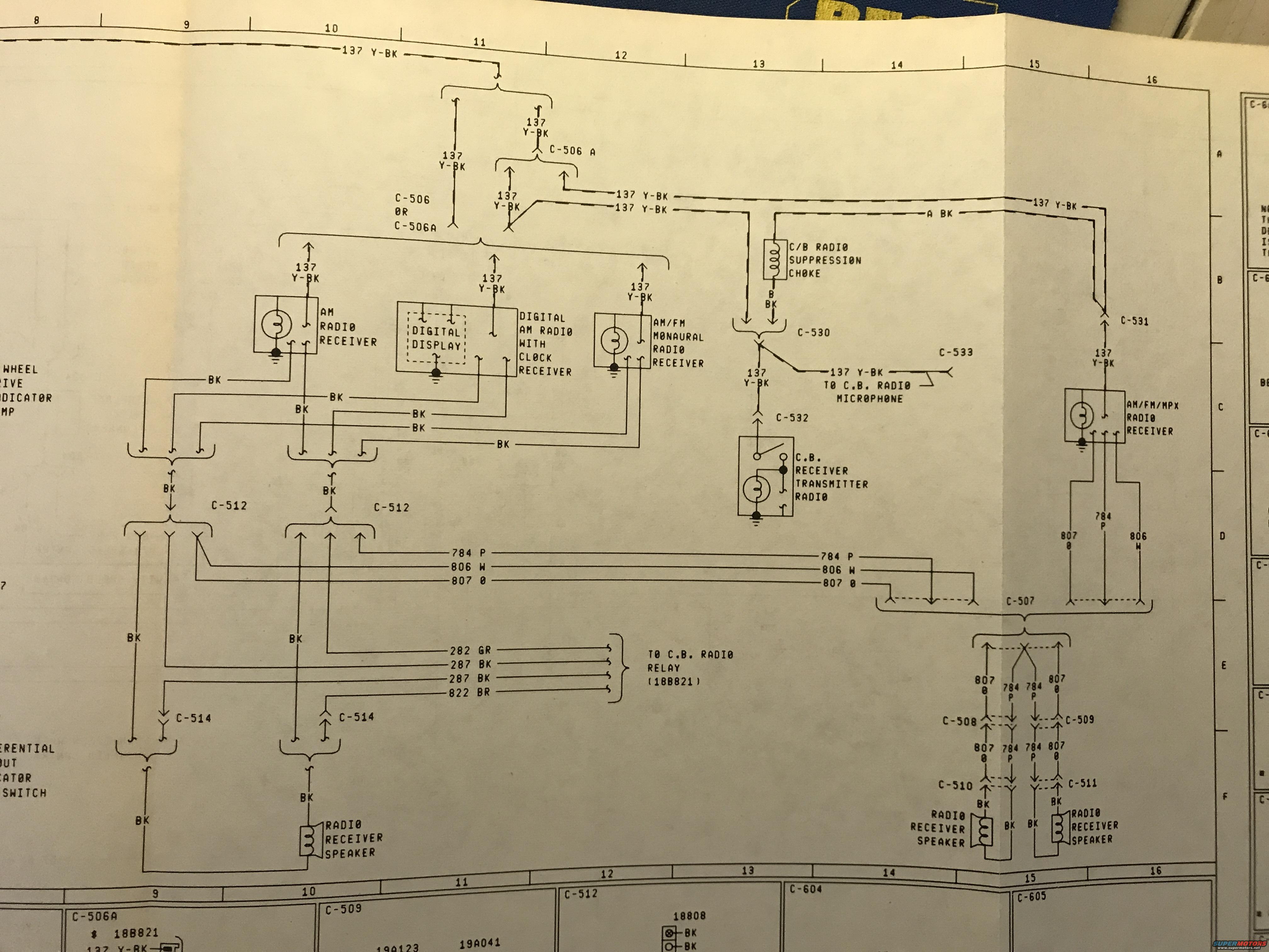
1979 Ford Bronco Radio & CB Wiring Diagram - AM/FM, Speakers, Connectors
Reference · 1978-1979 BroncoAll 116 wiring diagrams
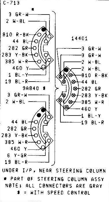
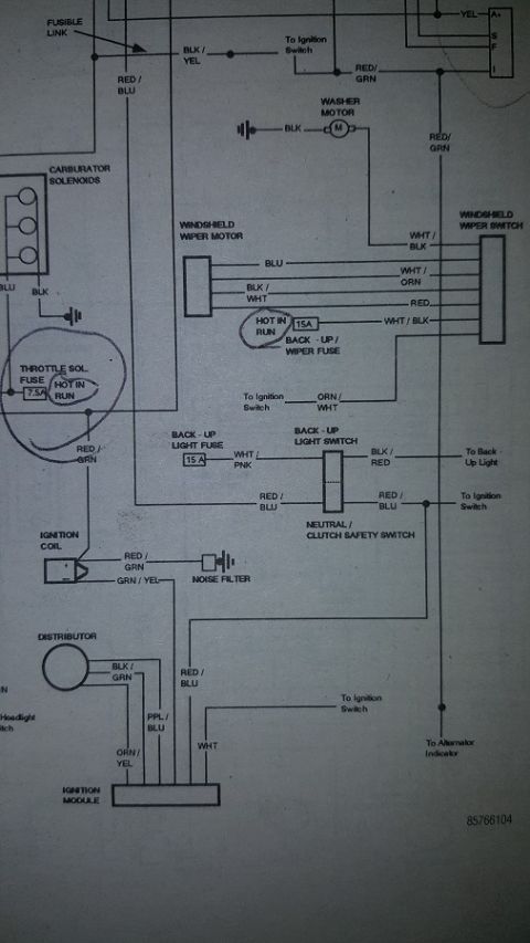
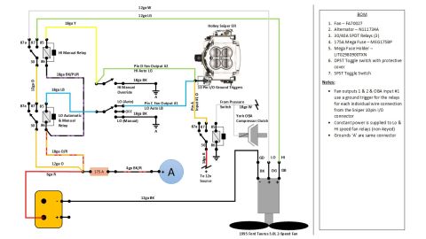
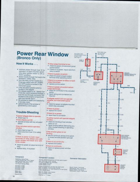
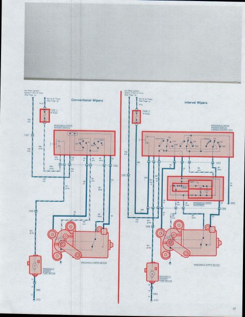
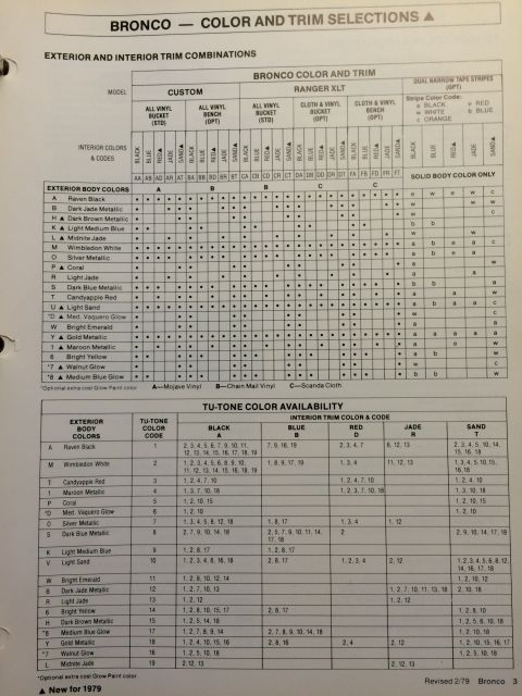
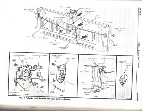
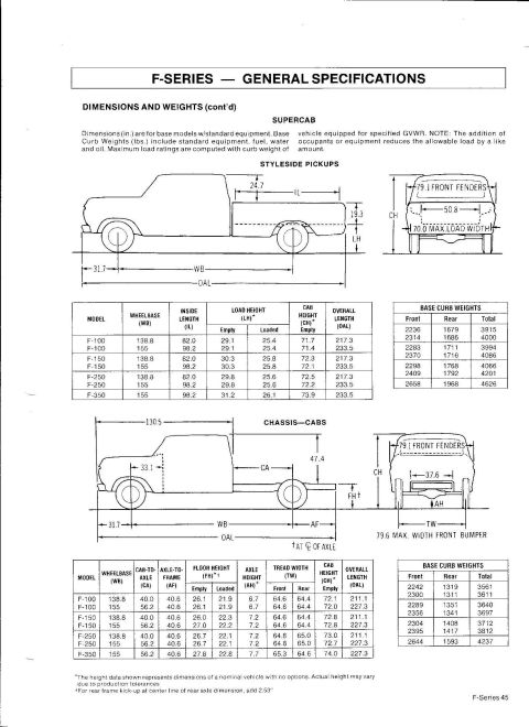


Wiring diagram of AM/FM radio and CB receiver circuits showing connectors, speakers and color-coded wires
Part of 1978-1979 Ford Bronco Wiring Diagrams
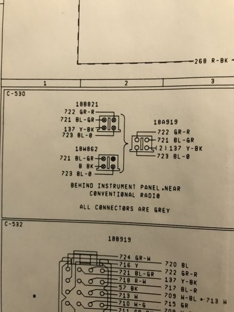
This is one page of a factory-style Ford wiring diagram covering the radio and audio system circuits. It shows the power feed circuit 137 (yellow with black stripe, "137 Y-BK") branching to several optional radio units: an AM radio receiver, a digital AM radio with clock receiver (with digital display), an AM/FM monaural radio receiver, an AM/FM/MPX (stereo multiplex) radio receiver, and a C.B. receiver/transmitter radio with its suppression choke and microphone connection. Connector numbers are identified throughout, including C-506/C-506A, C-507 through C-512, C-514, and C-530 through C-533. Speaker wiring is detailed with circuits 784 P (purple), 806 W (white), and 807 O (orange), routed through connectors C-508, C-509, C-510, and C-511 to left and right radio receiver speakers, with black (BK) ground returns. Additional circuits 282 GR, 287 BK, and 822 BR route to the C.B. radio relay (part reference 18B821). A partial legend strip at the bottom lists connector face views and part references such as 18B821, 19A123, 19A041, and 18808. A reader can use this page to trace radio power, ground, and speaker wiring by circuit number, wire color, and connector.
Is this accurate? Sign in to help verify it.
Frequently asked questions
- What wire color is the radio power feed circuit 137?
- Circuit 137 is Y-BK (yellow with black stripe), feeding all of the radio receiver options shown on the diagram.
- What circuit numbers and colors are used for the radio speakers?
- Speaker circuits are 784 P (purple), 806 W (white), and 807 O (orange), with BK (black) ground wires, routed through connectors C-508, C-509, C-510, and C-511.
- Which radio options are shown on this diagram?
- AM radio receiver, digital AM radio with clock receiver (with digital display), AM/FM monaural radio receiver, AM/FM/MPX radio receiver, and a C.B. receiver/transmitter radio with suppression choke and microphone.
- What circuits go to the C.B. radio relay?
- Circuits 282 GR, 287 BK, 287 BK, and 822 BR route to the C.B. radio relay, identified as part 18B821.
- Which connector serves the C.B. radio microphone?
- Connector C-533 with circuit 137 Y-BK is labeled 'TO C.B. RADIO MICROPHONE'.






No comments yet.