Home/
Registry/
Ford/
Bronco/
1978-1979/
“buyers guide”/
Photo
supermotors.net/registry/media/756763
Ford Tilt Steering Column Service - Wire Bale, Locking Lever & Pivot Pin 13-06-11

Reference · 1978-1979 BroncoAll 79 exploded parts diagrams
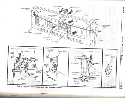
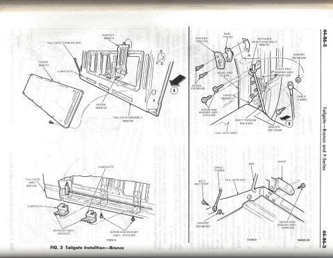
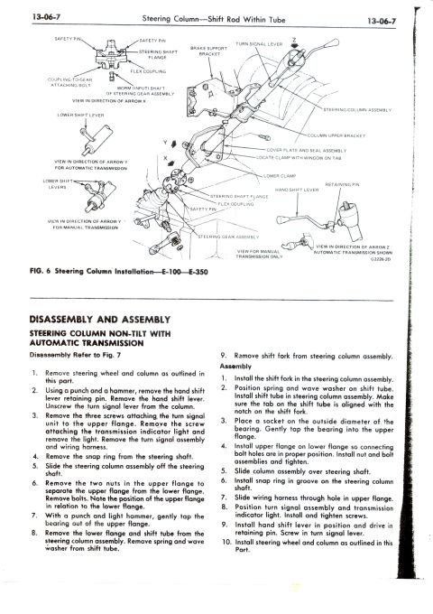
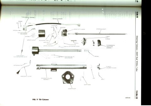
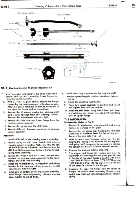
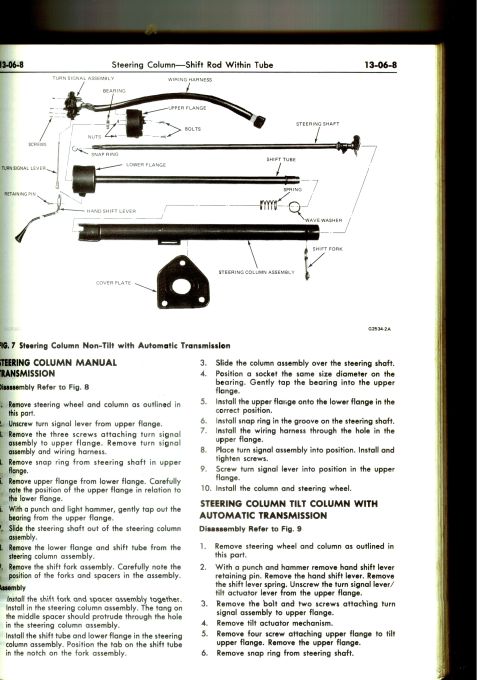
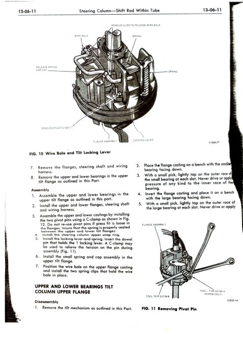
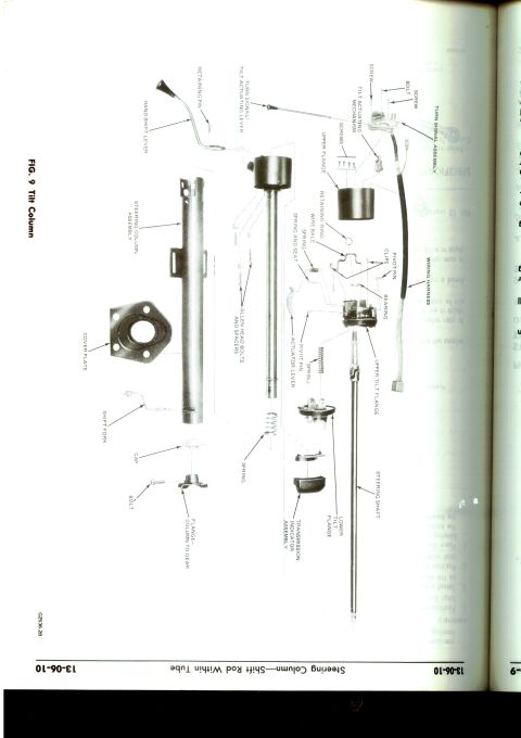


Ford steering column service (13-06-11): exploded view of wire bale, tilt locking lever, springs and flange bearings with Fig.11 pivot-pin removal using tool T70P-3D739-A.
Part of 1978-1979 Ford Bronco Exploded Parts Diagrams
This is page 13-06-11 of a Ford shop manual section titled "Steering Column: Shift Rod Within Tube," covering service of a tilt steering column. Figure 10 ("Wire Bale and Tilt Locking Lever") is an exploded/cutaway illustration identifying the wire bale, spring clips, springs, release spring and cap, flange assembly, locking lever, and the pin removed with a drift. The text finishes a disassembly procedure (removing the flanges, steering shaft, wiring harness, and the upper/lower bearings in the upper tilt flange) and gives a seven-step assembly procedure: installing bearings, flanges, steering shaft and wiring harness; joining the upper and lower castings with two pivot pins using a C-clamp (with a warning not to reuse pivot pins if the press fit is loose); installing the upper snap ring, locking lever, spring and dowel pin; installing the small spring and cap assembly; and positioning the wire bale with its two spring clips. A second section, "Upper and Lower Bearings Tilt Column Upper Flange," begins disassembly steps for removing the bearings by tapping the outer races with a small pick, cautioning never to drive on the inner races. Figure 11 ("Removing Pivot Pin") shows use of special tools T67P-3D739-B and T70P-3D739-A (screw only) on the flange assembly.
Is this accurate? Sign in to help verify it.
Frequently asked questions
- Can I reuse the pivot pins when assembling the tilt column castings?
- No. The manual states: do not re-use pivot pins if the press fit is loose in the flanges. The two pivot pins are installed using a C-clamp as shown in Fig. 12.
- What special tools are used to remove the tilt column pivot pin?
- Fig. 11 shows Tool T67P-3D739-B and Tool T70P-3D739-A (screw only) being used on the flange assembly to remove the pivot pin.
- How are the upper and lower bearings removed from the tilt column upper flange?
- Place the flange casting on a bench with the smaller bearing facing down and, with a small pick, lightly tap on the outer race of the small bearing at each slot. Then invert the casting with the large bearing facing down and tap the outer race of the large bearing at each slot. Never drive or apply pressure of any kind to the inner race of the bearing.
- How is the wire bale installed on the tilt column?
- Position the wire bale on the upper flange casting and install the two spring clips that hold the wire bale in place (see Fig. 10).
- How is tension relieved on the locking lever dowel pin during assembly?
- A C-clamp may be used to relieve the tension on the pin during assembly, as shown in Fig. 11.






No comments yet.