Home/
Registry/
Ford/
Bronco/
1978-1979/
“buyers guide”/
Photo
supermotors.net/registry/media/756765
Ford Tilt Steering Column Disassembly & Assembly - Shift Rod Within Tube 13-06-9

Reference · 1978-1979 BroncoAll 79 exploded parts diagrams
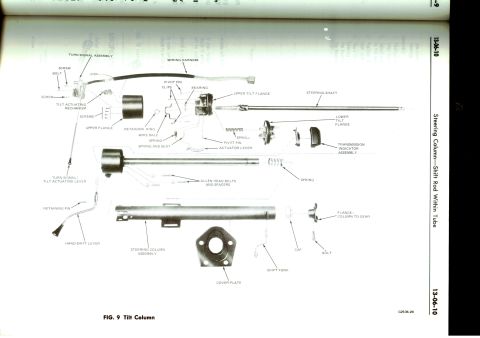
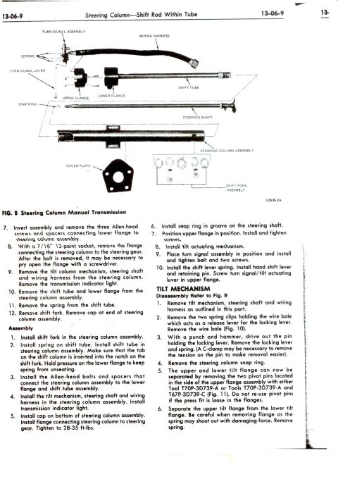
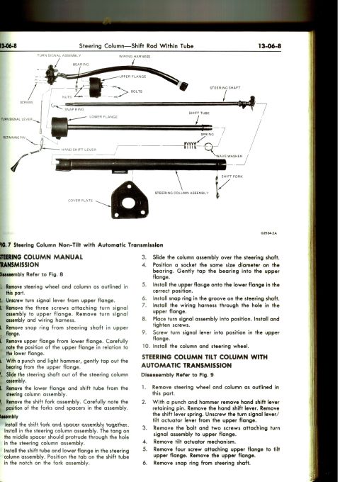
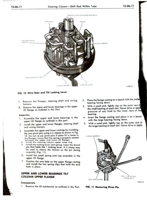
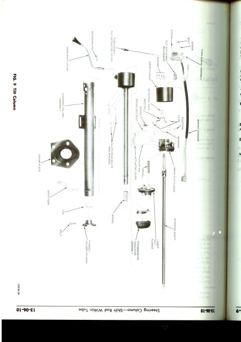
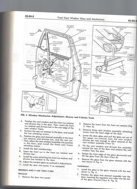
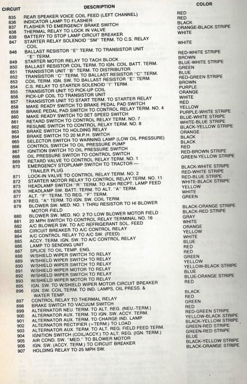
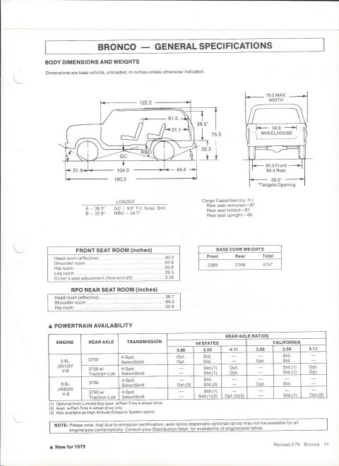
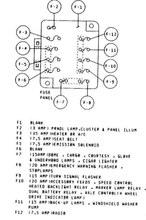


Ford steering column service (13-06-9, Fig.8): manual-transmission column exploded view with shift tube, flanges, fork and tilt mechanism; column-to-gear flange torque 28-35 ft-lbs.
Part of 1978-1979 Ford Bronco Exploded Parts Diagrams
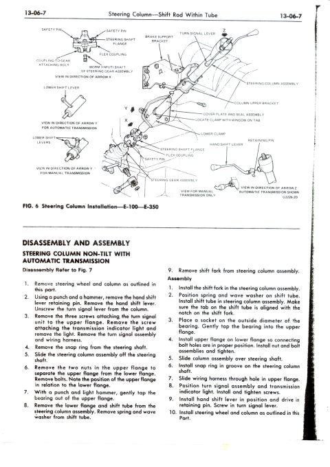
This is page 13-06-9 of a Ford shop manual section titled "Steering Column: Shift Rod Within Tube." The top half shows Fig. 8, an exploded parts illustration (illustration code G2535-2A) of a steering column for a manual transmission, with labeled components: turn signal assembly, wiring harness, screws, turn signal lever, upper flange, lower flange, shift tube, snap ring, steering shaft, steering column assembly, cover plate, and shift fork assembly. The text continues disassembly steps 7-12 (removing Allen-head screws, the flange to the steering gear using a 7/16" 12-point socket, the tilt column mechanism, shift tube, spring, and shift fork), followed by a 10-step assembly procedure that includes torquing the steering column-to-steering gear flange to 28-35 ft-lbs. The page then begins the Tilt Mechanism disassembly procedure (referencing Figs. 9-11), covering removal of the wire bale and spring clips, driving out the locking lever pin, removing the steering column snap ring, and separating the upper and lower tilt flanges using special tools T70P-3D739-A and T67P-3D739-C, with cautions not to re-use loose-fitting pivot pins and to watch for the spring under tension.
Is this accurate? Sign in to help verify it.
Frequently asked questions
- What torque is specified for the flange connecting the steering column to the steering gear?
- Tighten to 28-35 ft-lbs.
- What socket is needed to remove the flange connecting the steering column to the steering gear?
- A 7/16" 12-point socket. After the bolt is removed, it may be necessary to pry open the flange with a screwdriver.
- What special tools are used to remove the tilt flange pivot pins?
- Tool T70P-3D739-A, or Tools T70P-3D739-A and T67P-3D739-C (Fig. 11). Do not re-use pivot pins if the press fit is loose in the flanges.
- What caution applies when separating the upper and lower tilt flanges?
- Be careful when removing the flange, as the spring may shoot out with damaging force.
- What parts are shown in the exploded steering column diagram (Fig. 8)?
- Turn signal assembly, wiring harness, screws, turn signal lever, upper flange, lower flange, shift tube, snap ring, steering shaft, steering column assembly, cover plate, and shift fork assembly.






No comments yet.