Home/
Registry/
Ford/
Ranchero/
1972-1976/
1972 Ford Ranchero/
Photo
supermotors.net/registry/media/819230
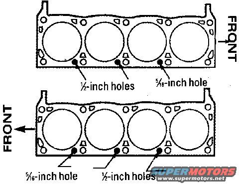
Ford 351C Head Gasket Orientation Diagram - 1/2" & 5/16" Coolant Hole Locations
Reference · 1972-1976 RancheroAll 31 manual pages
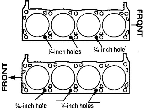
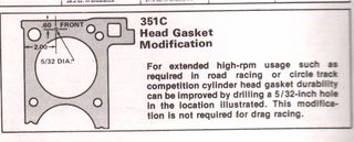
Service manual figure of a head gasket identifying coolant hole sizes and the front-facing installation orientation.
Part of 1972-1976 Ford Ranchero Manual Pages
This document is a scanned illustration showing two engine cylinder head gasket outlines, each depicting four cylinder bore openings and various smaller bolt and coolant passage holes. The purpose of the diagram is to identify the size and location of specific coolant passage holes so the gaskets can be oriented correctly during installation. On the upper gasket, whose "FRONT" is marked at the right side, two marked holes are labeled as ½-inch holes and one is labeled as a 5⁄16-inch hole. On the lower gasket, whose "FRONT" is marked at the left side with an arrow, one marked hole is labeled as a 5⁄16-inch hole and two marked holes are labeled as ½-inch holes. A reader can learn how to distinguish gasket orientation (and left versus right bank placement) by comparing the positions of the ½-inch and 5⁄16-inch holes relative to the front of the engine. The diagram contains no text identifying a specific year, make, model, or engine, though the uploader filed it with other Ford 351 Cleveland reference material for a 1972 Ford Ranchero. No part numbers, torque values, or additional specifications appear in the scan.
Is this accurate? Sign in to help verify it.
Frequently asked questions
- How do I tell which way the head gasket should face?
- The diagram marks 'FRONT' on each gasket and shows the coolant hole pattern: with the gasket oriented correctly, the ½-inch holes and the single 5⁄16-inch hole fall in specific positions along the gasket edge, letting you verify orientation before installation.
- What size are the coolant holes shown on the gaskets?
- The diagram identifies two hole sizes: ½-inch holes (two marked per gasket) and a single 5⁄16-inch hole per gasket.
- Are the two gaskets in the diagram oriented the same way?
- No. The upper gasket is shown with FRONT to the right, while the lower gasket is shown with FRONT to the left (indicated by an arrow), demonstrating how the hole pattern appears for each orientation.
- Does this document give torque specs or part numbers for the head gaskets?
- No. The scan only shows the gasket outlines with FRONT orientation labels and the ½-inch and 5⁄16-inch hole callouts; no torque values or part numbers are visible.

No comments yet.