SuperMotors SuperMotors SUPERMOTORS Search: try “orange Bronco on 35s”
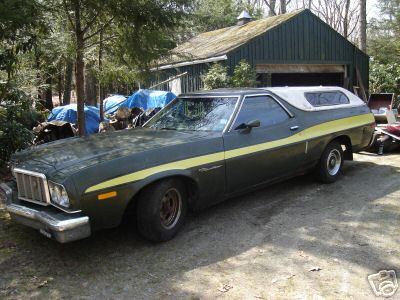
Home/ Registry/ Ford/ Ranchero/ 1972-1976/ 1972 Ford Ranchero/ Photo supermotors.net/registry/media/859547

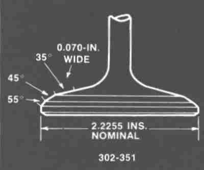
Ford 302/351 Valve Angle Diagram - 35°/45°/55° Cut, 2.2255 in. Intake Valve

Dimensioned valve cross-section showing 35, 45 and 55 degree seat angles
Dimensioned valve cross-section showing 35, 45 and 55 degree seat anglesOriginal file
Dimensioned valve cross-section showing 35, 45 and 55 degree seat angles

Reference · 1972-1976 RancheroAll 31 manual pages
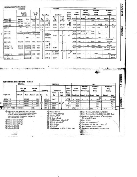
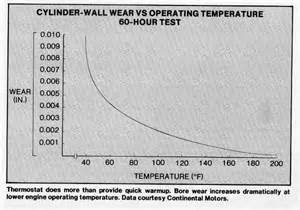
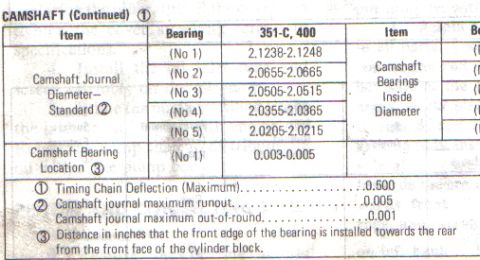
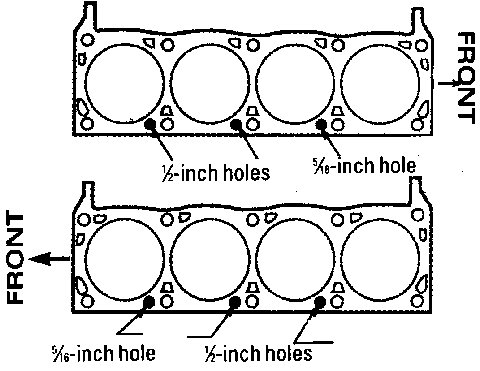
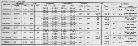
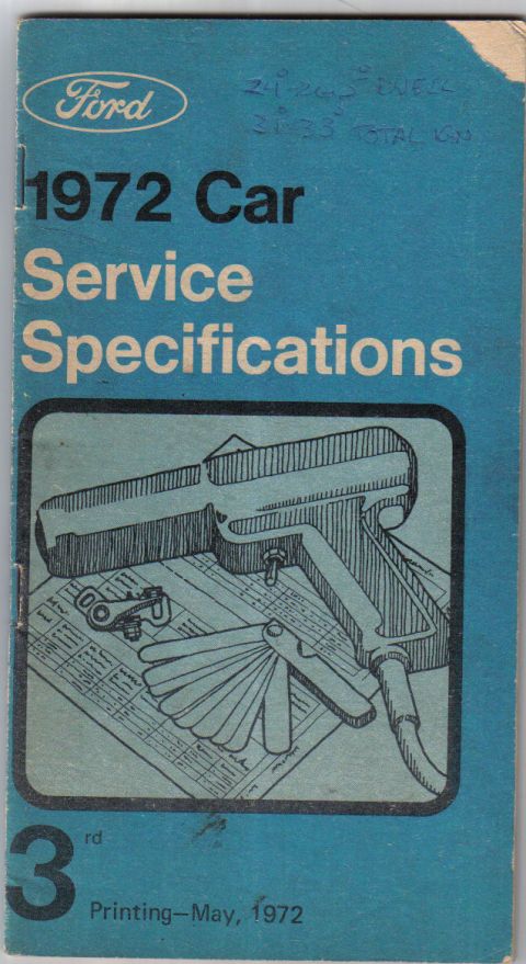
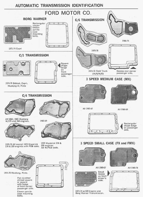
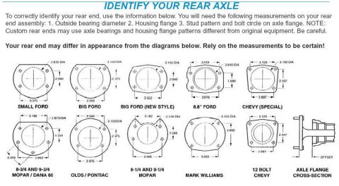
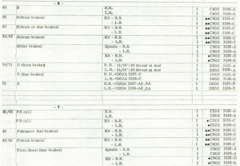
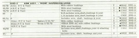
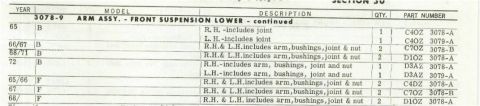
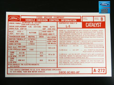
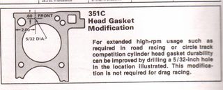
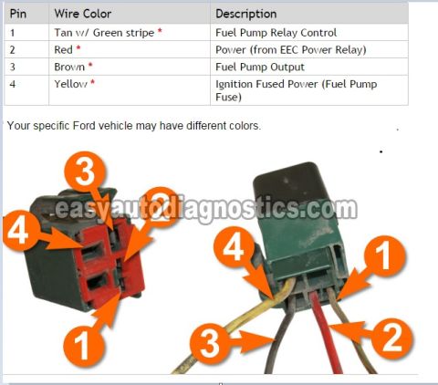
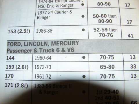
Ford Group 21 engine performance specifications tables with idle rpm, ignition timing and choke settings Cylinder Wall Wear vs Engine Operating Temperature Graph - 60-Hour Test Chart 351-C and 400 camshaft journal diameter and bearing location specification table Ford 302/351 Valve Angle Diagram - 35°/45°/55° Cut, 2.2255 in. Intake Valve Ford 351C Head Gasket Orientation Diagram - 1/2" & 5/16" Coolant Hole Locations Camshaft I.D. and application table for 351 C, 351 CJ, Boss, HO and 400 engines with valve timing and lift Ford 1972 Car Service Specifications booklet cover, 3rd printing Ford Automatic Transmission ID Guide - C4, C6, FMX, C3 Pan Shapes 1960-78 Rear Axle Identification Chart - Ford, Chevy, Mopar Housing Flange Dimensions Ford parts catalog page of '65-'72 3105/3106 R.H. and L.H. spindle part numbers for drum and disc brakes Ford parts catalog page for 3082-3 front suspension upper arm assemblies, '65-'72, rubber and steel bushings Ford parts catalog page for 3078-9 front suspension lower arm assemblies, '65-'72, with part numbers 31manual pages1972-1976 Ford Ranchero More reference Reproduction 1978 Ford 351M/400 emission control decal D8OE-9C485-AF, 12°BTDC timing, catalystSpec plate CAR CRAFT January 1962 magazine cover featuring a custom yellow carBrochure Manual transmission exploded parts breakdown with numbered callouts for case, gears, shafts and shift forksExploded parts Ford 351 Cleveland V8 Oiling System Diagram - Oil Flow Sketch (Mains, Cam, Lifters)Schematic Ford 351C Screw-In Rocker Stud Conversion Blueprint - Boss Machining SpecsBlueprint Ford 351C Cleveland Head Gasket Modification - 5/32 Hole Drilling DiagramService procedure Ford Fuel Pump Relay Connector Pinout - Wire Colors & Pin FunctionsWiring diagram Engine spec table for Ford, Lincoln, Mercury passenger and truck 6 and V6 engines by displacement and yearTorque spec

Manual diagram of a valve cross-section with seat angles, 0.070-in width, and 2.2255-in nominal head diameter.

Part of 1972-1976 Ford Ranchero Manual Pages

AI caption · Photo 764 of 1000

This document is a single technical illustration showing a cross-section diagram of an engine valve, labeled "302-351" (indicating applicability to Ford 302 and 351 cubic-inch engines). The diagram depicts the valve head in profile with three angle callouts on the valve face/margin area: 35°, 45°, and 55°, arranged from the upper face toward the outer edge. A callout indicates a seating/contact band that is 0.070 inches wide. The overall valve head diameter is dimensioned across the bottom of the drawing as 2.2255 inches nominal. From this diagram a reader can learn the multi-angle valve face/seat geometry (35°/45°/55°) used when grinding or machining valves and seats for these engines, the specified width of the 0.070-inch contact band, and the nominal 2.2255-inch head diameter, which corresponds to an intake valve size. The image appears to be reproduced from a factory or aftermarket engine service manual and was uploaded as part of an album of Ford engine reference pages (head gaskets, distributor specs, firing orders, service specifications) for a 1972 Ford Ranchero.

Is this accurate? Sign in to help verify it.

Frequently asked questions

What valve angles are shown for the Ford 302/351 valve?
The diagram shows three angles on the valve: 35°, 45°, and 55°.
How wide is the valve contact/seat band on the 302-351 valve?
The diagram specifies a band 0.070 inches wide.
What is the nominal valve head diameter shown in the diagram?
2.2255 inches nominal.
Which engines does this valve diagram apply to?
The diagram is labeled "302-351", indicating it applies to 302 and 351 engines.
Comments

No comments yet.

More 1972-1976 Rancheros