Ford 3G alternator exploded parts diagram, 95A side-mount V8 dri…
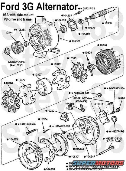
Ford 3G (3rd Generation) Alternator Exploded
N807805-S368 - Pulley Nut
10344 - Pulley
108384 - Cardboard Tube
10A351 - Drive End Frame (this style is the side-mount used mostly on V8s; the 4 holes between the front rib pairs indicates 95A output)
10A303 - Bearing, front
10A355 - Bearing Retainer, front
389217-S2 - Screw
10A360 - Spacer
10380 - Snap Ring
10330 - Shaft
10380 - Fan
10379 - Core
10327 - Armature Winding
10328 - Commutator (Slip Rings)
10368 - Stator Winding
10A378 - Sheild
N811303-S36 - Output Stud
10A318 - Rectifier Plate
10374 - Diode
108301 - Rectifier
N80676-S30 - Nut
10A304 - Bearing, rear
10260 - Brush Holder Assembly
10A349 - Rear End Frame
N805910-S101 - Case Bolt
10A383 - Output Adapter (optional)
N805481-S36 - Output Nut
10316 - Voltage Regulator Assembly Motorcraft GR821
N805911-S7M - Regulator Screw
N807423-S36 - Brush Screw
10563 - Screw Cap
N807749-S - Bearing Cap
The rear case & stator can be rotated (clocked) to 3 positions relative to the front case to orient the connectors for ease of installation. EITHER: the pulley must be removed first so the rotor can remain in the rear case while the stator is pushed back out of the front case; OR: the regulator must be removed, the brushes pinned, and then reinstalled after the case has been clocked. Since the stator wires are attached to the rectifier, and the rectifier is attached to the output stud, the stator MUST move with the rear case at all times.
See also: .
.  .
.  .
.  .
.  .
.  .
.  .
.  .
.  .
. 
Is this accurate? Sign in to help verify it.
Comments
More from this build


No comments yet.