Home/
Registry/
Ford/
Mustang/
1964-1973/
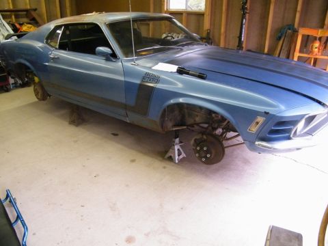
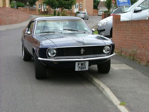
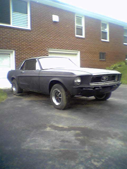
1967 Ford Mustang/
Photo
supermotors.net/registry/media/922984
Ford M-12071-E302/H302 5.0 EFI Engine Harness Diagram - Connector & Wire Colors
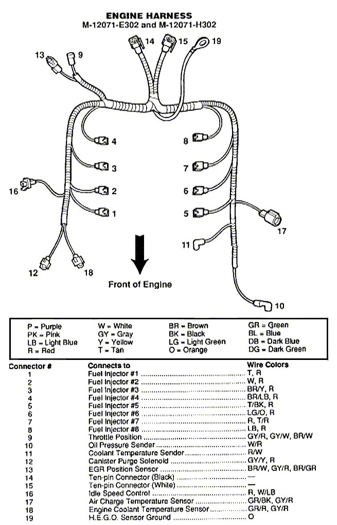
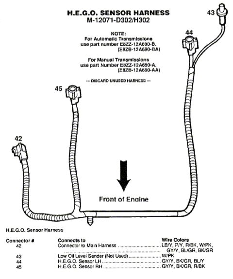
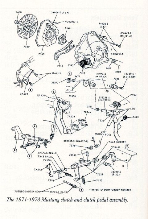
Reference · 1964-1973 MustangAll 4 exploded parts diagrams
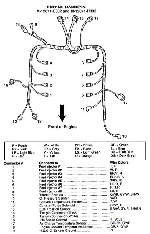
Engine wiring harness layout (M-12071-E302/H302) with a connector-by-connector table mapping 8 fuel injectors, TPS, ECT, IAC and sensors to specific wire colors.
Part of 1964-1973 Ford Mustang Exploded Parts Diagrams
This document is a labeled diagram and connector chart for the Ford engine wiring harness, part numbers M-12071-E302 and M-12071-H302 (Ford Racing/Motorsport EFI 302 engine harnesses). The top of the page shows an illustration of the harness laid out relative to the front of the engine, with 19 numbered connector callouts. Below the illustration is a wire color abbreviation legend (P=Purple, PK=Pink, LB=Light Blue, R=Red, W=White, GY=Gray, Y=Yellow, T=Tan, BR=Brown, BK=Black, LG=Light Green, O=Orange, GR=Green, BL=Blue, DB=Dark Blue, DG=Dark Green). A table then identifies each numbered connector, what it connects to, and its wire colors: connectors 1-8 serve fuel injectors #1-#8 (each with a red wire plus a unique color), connector 9 is the Throttle Position sensor, 10 the Oil Pressure Sender, 11 the Coolant Temperature Sender, 12 the Canister Purge Solenoid, 13 the EGR Position Sensor, 14 and 15 the ten-pin (black and white) connectors, 16 the Idle Speed Control, 17 the Air Charge Temperature Sensor, 18 the Engine Coolant Temperature Sensor, and 19 the H.E.G.O. sensor ground. Readers can use this to identify connectors and verify wire colors when installing or troubleshooting this EFI engine harness.
Is this accurate? Sign in to help verify it.
Frequently asked questions
- What part numbers does this engine harness diagram cover?
- It covers Ford engine harnesses M-12071-E302 and M-12071-H302.
- What wire colors go to the fuel injectors on this harness?
- Each injector has a red (R) wire plus one unique wire: #1 Tan, #2 White, #3 Brown/Yellow, #4 Brown/Light Blue, #5 Tan/Black, #6 Light Green/Orange, #7 Tan/Red (listed as R, T/R), #8 Light Blue.
- Which wire colors connect to the Throttle Position sensor?
- Connector 9 (Throttle Position) uses Gray/Red, Gray/White, and Brown/White wires.
- What are connectors 14 and 15 on this harness?
- Connector 14 is the ten-pin connector (Black) and connector 15 is the ten-pin connector (White); no wire colors are listed for them.
- What is connector 19 on the harness?
- Connector 19 is the H.E.G.O. sensor ground, with an orange (O) wire.
No comments yet.