Home/
Registry/
Ford/
Mustang/
1964-1973/
“Race Car Tope”/
Photo
supermotors.net/registry/media/879700
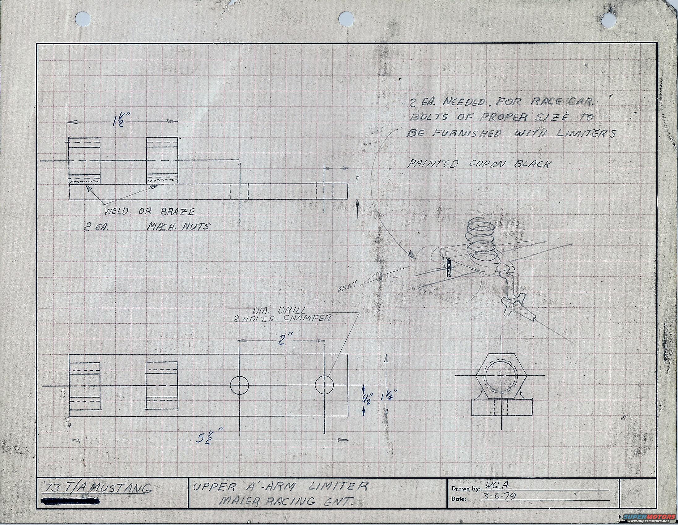
1973 Mustang Trans-Am Upper A-Arm Limiter Blueprint - Maier Racing (1979)
Reference · 1964-1973 MustangAll 11 blueprints
Engineering drawing of a 1973 Mustang upper A-arm limiter with dimensions, weld/drill notes, and fabrication specifications.
Part of 1964-1973 Ford Mustang Blueprints
This document is a hand-drawn fabrication blueprint on graph paper, dated 3-6-79 and drawn by "W.G.A.", for an "Upper A-Arm Limiter" for a '73 T/A (Trans-Am) Mustang, attributed to Maier Racing Ent. The drawing shows a rectangular plate/bar approximately 5 1/2 inches long and 1 1/4 inches wide, with two holes drilled and chamfered on 2-inch centers (5/8-inch dimension noted from edge/centerline). Two machine nuts, spaced 1 1/2 inches apart, are to be welded or brazed onto the plate (2 each). A detail view shows a hex nut welded to the plate. A pencil sketch at right illustrates the limiter's installed position relative to the front coil spring and upper control arm, with the front direction indicated. Handwritten notes state that 2 units are needed for the race car, that bolts of proper size are to be furnished with the limiters, and that the parts are to be painted "copon" black. A reader can learn the dimensions and fabrication method (weld or braze nuts, drill and chamfer holes) needed to reproduce this suspension travel limiter for a 1973 Trans-Am racing Mustang.
Is this accurate? Sign in to help verify it.
Frequently asked questions
- What vehicle is this upper A-arm limiter blueprint for?
- The title block identifies it as for a '73 T/A (Trans-Am) Mustang, by Maier Racing Ent.
- What are the main dimensions of the limiter plate?
- The plate is 5 1/2" long with two drilled and chamfered holes spaced 2" apart, a 1 1/4" width dimension with a 5/8" hole offset, and the two machine nuts are spaced 1 1/2" apart.
- How are the nuts attached to the limiter plate?
- The drawing calls out "WELD OR BRAZE, 2 EA. MACH. NUTS", two machine nuts are to be welded or brazed onto the plate.
- How many limiters are needed and what finish is specified?
- The notes state "2 EA. NEEDED FOR RACE CAR" and that they are to be "PAINTED COPON BLACK." Bolts of proper size are to be furnished with the limiters.
- Who drew this blueprint and when?
- It was drawn by "W.G.A." and dated 3-6-79.
No comments yet.