Home/
Registry/
Ford/
Mustang/
1964-1973/
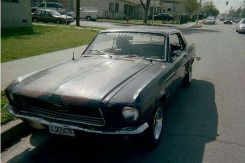
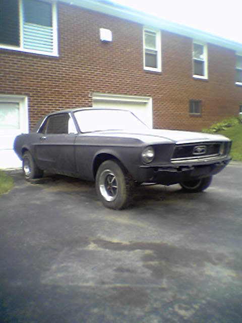
1967 Ford Mustang/
Photo
supermotors.net/registry/media/922985
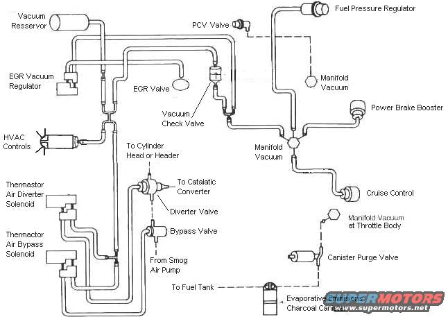
Ford Mustang 5.0 Vacuum Line Routing Diagram - EGR, Thermactor & EVAP Hoses
Reference · 1964-1973 MustangAll 2 vacuum routing diagrams
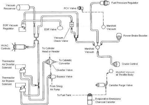
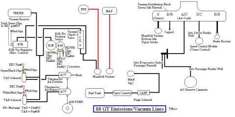
Vacuum routing schematic linking PCV valve, EGR valve/regulator, fuel pressure regulator, power brake booster, thermactor diverter/bypass solenoids, cruise control and canister purge valve.
Part of 1964-1973 Ford Mustang Vacuum Routing Diagrams
This document is a labeled vacuum routing diagram for a Ford engine, showing the layout and interconnection of vacuum lines among emissions and accessory components. Depicted components include the vacuum reservoir (spelled 'Resservor'), PCV valve, fuel pressure regulator, EGR vacuum regulator, EGR valve, vacuum check valve, power brake booster, HVAC controls, cruise control, and two manifold vacuum source points (one noted as manifold vacuum at the throttle body). The Thermactor secondary air injection system is shown in detail, including the Thermactor air diverter solenoid (spelled 'Thermastor'), Thermactor air bypass solenoid, diverter valve, and bypass valve, with routing 'To Cylinder Head or Header,' 'To Catalatic Converter,' and 'From Smog Air Pump.' The evaporative emissions system is also illustrated, showing the canister purge valve, the evaporative emissions charcoal canister (spelled 'Emmisions'), and a line 'To Fuel Tank.' Solid lines appear to represent vacuum hoses while dashed lines indicate connections to vacuum sources or component references. A reader can use this diagram to identify each vacuum-operated component and trace how vacuum hoses should be routed between them. The diagram contains no part numbers, dates, or explicit vehicle year/model identification within the image itself.
Is this accurate? Sign in to help verify it.
Frequently asked questions
- What components are shown on this Ford vacuum routing diagram?
- It shows the vacuum reservoir, PCV valve, fuel pressure regulator, EGR vacuum regulator, EGR valve, vacuum check valve, power brake booster, HVAC controls, cruise control, Thermactor air diverter and bypass solenoids, diverter valve, bypass valve, canister purge valve, and evaporative emissions charcoal canister.
- Where does the Thermactor air system route air according to the diagram?
- Air comes 'From Smog Air Pump' through the bypass valve and diverter valve, and is routed 'To Cylinder Head or Header' and 'To Catalatic Converter' (as spelled in the diagram).
- Where do the vacuum sources come from in this diagram?
- The diagram labels manifold vacuum in multiple places, including a point labeled 'Manifold Vacuum at Throttle Body,' which feeds components like the power brake booster, cruise control, and canister purge valve.
- How is the evaporative emissions system connected?
- The canister purge valve connects to manifold vacuum at the throttle body and to the evaporative emissions charcoal canister, which has a line running 'To Fuel Tank.'
- What controls the EGR valve vacuum in this diagram?
- The EGR vacuum regulator is shown in the vacuum circuit leading to the EGR valve, with a vacuum check valve also shown in the system near the PCV valve.
No comments yet.