SuperMotors SuperMotors SUPERMOTORS Search: try “orange Bronco on 35s”
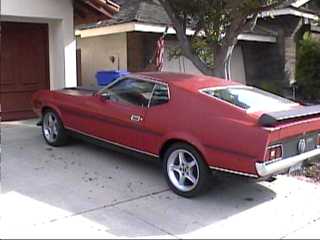
Home/ Registry/ Ford/ Mustang/ 1964-1973/ 1967 Ford Mustang/ Photo supermotors.net/registry/media/922988

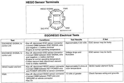
HEGO sensor terminal pinout with HEGO SIGNAL, PWR, SIG RTN and G…
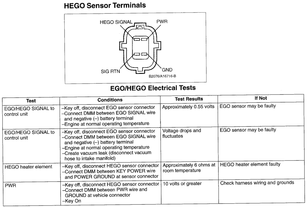
HEGO sensor terminal pinout with HEGO SIGNAL, PWR, SIG RTN and GND plus EGO/HEGO electrical test table
HEGO sensor terminal pinout with HEGO SIGNAL, PWR, SIG RTN and GND plus EGO/HEGO electrical test tableOriginal file
HEGO sensor terminal pinout with HEGO SIGNAL, PWR, SIG RTN and GND plus EGO/HEGO electrical test table

Reference · 1964-1973 MustangAll 10 wiring diagrams
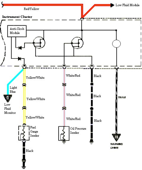
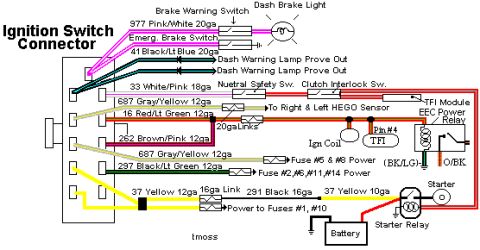
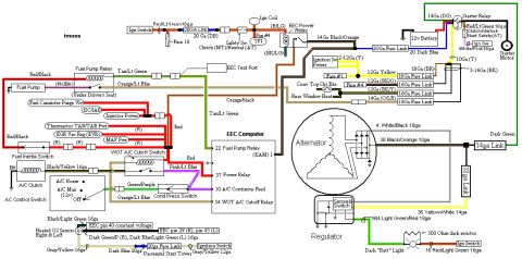
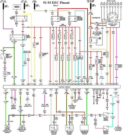
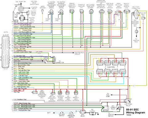
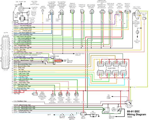
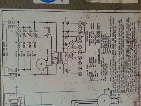
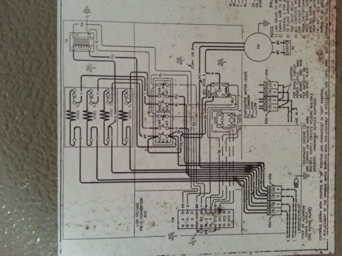
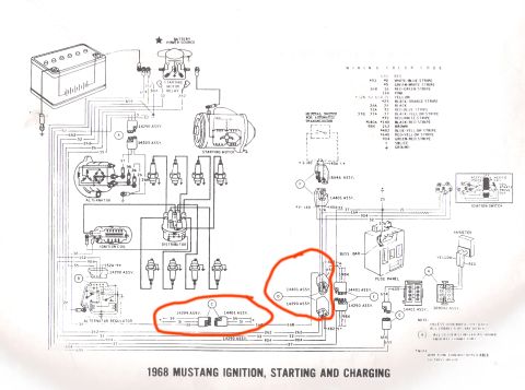
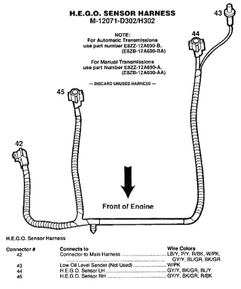
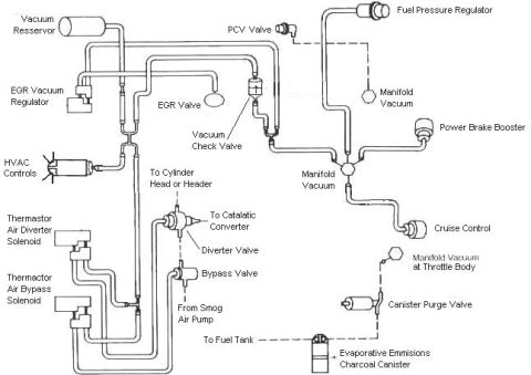
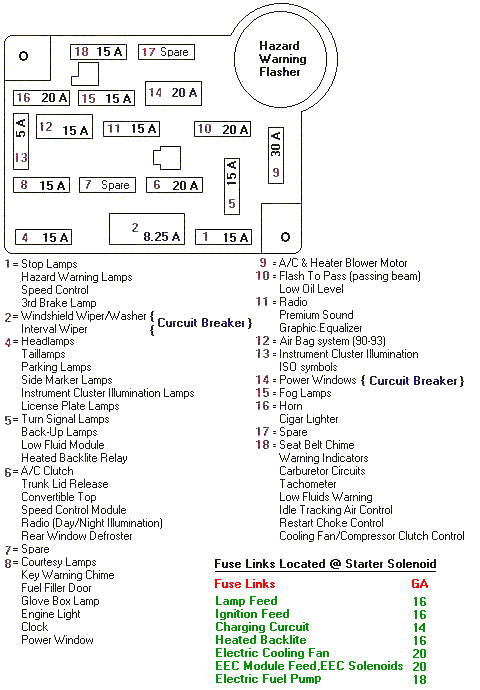
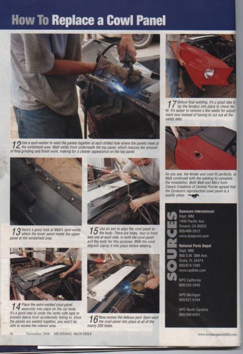
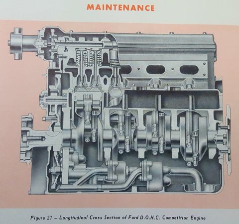
HEGO sensor terminal pinout with HEGO SIGNAL, PWR, SIG RTN and GND plus EGO/HEGO electrical test table Ford Mustang Fuel Gauge Sender & Anti-Slosh Module Wiring Diagram - Wire Colors Ford Mustang Ignition Switch Connector Wiring Diagram - Wire Colors & Circuits Ford Mustang 5.0 EEC Wiring Diagram - Fuel Pump, Alternator, Fuse Links, A/C 1991-93 Ford Mustang 5.0 EEC-IV Pinout & Wiring Diagram - ECU Pin Colors 1988-1991 Ford Mustang 5.0 EEC-IV Wiring Diagram - 60-Pin ECU Pinout & Colors 1988-1991 Ford Mustang 5.0 EEC-IV Wiring Diagram - 60-Pin ECU Pinout & Colors Electric Heat Air Handler Wiring Diagram B17576-02 - 208/230V Schematic & Notes Electric Heat Air Handler Wiring Diagram - HTR, BTDR, EHR, 60A Breakers 1968 Ford Mustang Ignition, Starting & Charging Wiring Diagram + Color Codes 10wiring diagrams1964-1973 Ford Mustang More reference Ford H.E.G.O. O2 Sensor Harness Diagram M-12071-D302/H302: Connectors & WiresExploded parts Ford Mustang 5.0 Vacuum Line Routing Diagram - EGR, Thermactor & EVAP HosesVacuum routing Ford Mustang Fox Body Fuse Box Diagram - Fuse Panel Layout & Fusible LinksFuse chart American Autowire Classic Update Wiring Kit Unboxing - 1968 Ford MustangBrochure '65 Mustang door data plate with body 63A, color J, trim 26, DSO 51 and axle/trans codesSpec plate Ford 427 SOHC & GT Engine Induction System Development - Cylinder Head DesignManual page 1973 Mustang Trans-Am Upper A-Arm Limiter Blueprint - Maier Racing (1979)Blueprint Mustang Monthly how-to article on replacing a cowl panel with numbered welding step photos and parts sourcesService procedure Ford DOHC Competition Engine Longitudinal Cross Section Diagram - Figure 21Schematic

HEGO sensor connector pinout (B2076/A16716-B) with an EGO/HEGO test table: about 0.55 volts signal, about 6 ohms heater, 10 volts or greater PWR.

Part of 1964-1973 Ford Mustang Wiring Diagrams

AI caption · Photo 19 of 20

HEGO Sensor Terminals HEGO SIGNAL PWR SIG HTN 6ND Ems/Manes EGO/HEGO Electrical Tests 'I'III Oondlllont Tan leh If M EGO/HEGO SIGNAL lo Key all, alsoonnecl EGO sensor connector Approxlmalely 0.55 volts EGO sensor may be faulty comml unit Connect DMM bemeen EGO SIGNAL wire and negalive () ballery terrnlnal Englne all normal operating temperature 1 EGO/HEGO SIGNAL to Key 01f, disconnect EGO sensor connemor Voltage drops and E60 sensor may be Ioulty control unit Connecl DMM between EGO SIGNAL wire uctuates and negallve () battery lerrnlnal -Englne al normal operating lemperahure Create vaouum leak (dleconnect vacuum nose to intake manifold) HEGO heater element Key all, disconnect HEGO sensor connector Approximalely 6 ohms at HEGO healer element faulty -Connect DMM between KEV POWER wire room temperature and POWER GROUND a! sensor connector PWH Key all. dlsconnecl HEGO sensor connector 10 volts or greater Check hamm wiring and grounds tanned DMM between PWR wire and GROUND at vehicle conneclor Key On

Is this accurate? Sign in to help verify it.
Comments

No comments yet.

More 1964-1973 Mustangs