Home/
Registry/
Ford/
Mustang/
1964-1973/
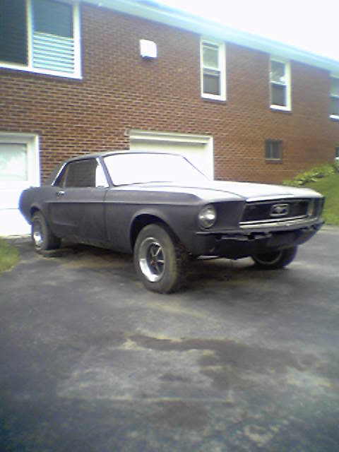
1967 Ford Mustang/
Photo
supermotors.net/registry/media/922979
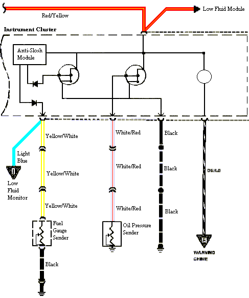
Ford Mustang Fuel Gauge Sender & Anti-Slosh Module Wiring Diagram - Wire Colors
Reference · 1964-1973 MustangAll 10 wiring diagrams
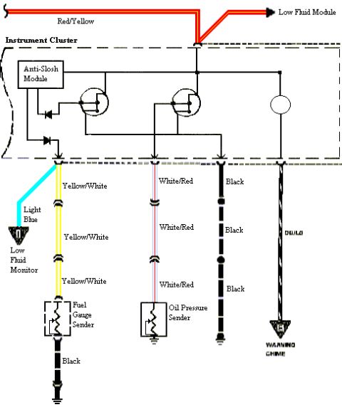
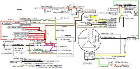
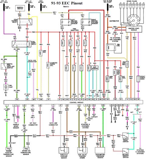
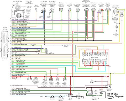
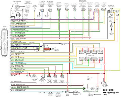
Wiring diagram of the instrument cluster showing fuel gauge sender, oil pressure sender, low fluid monitor and warning chime circuits with wire colors.
Part of 1964-1973 Ford Mustang Wiring Diagrams
This is a hand-traced color wiring diagram showing the fuel gauge sender and related instrument cluster circuits for a Ford Mustang. At the top, a Red/Yellow wire feeds the Low Fluid Module. Inside the dashed box labeled 'Instrument Cluster' is the Anti-Slosh Module along with the fuel gauge, another gauge, and an indicator lamp (drawn as circles). Below the cluster connector, four circuits run downward: a Light Blue wire to the Low Fluid Monitor; a Yellow/White wire (shown with in-line connectors) to the Fuel Gauge Sender, which is then grounded through a Black wire; a White/Red wire (also with in-line connectors) to the Oil Pressure Sender, which grounds at the sender; a Black ground wire path; and a striped DG/LG wire to the Warning Chime. The diagram lets a reader identify wire colors for the fuel level sending unit, low fuel warning, oil pressure gauge, and warning chime circuits, and shows where connectors and grounds occur along each run. No year, part numbers, or connector pin numbers are printed on the diagram itself.
Is this accurate? Sign in to help verify it.
Frequently asked questions
- What wire color goes to the Mustang fuel gauge sender?
- A Yellow/White wire runs from the instrument cluster down to the Fuel Gauge Sender, which is then grounded through a Black wire.
- What color wire feeds the oil pressure sender?
- A White/Red wire runs from the instrument cluster to the Oil Pressure Sender, which grounds at the sender.
- What wire color connects to the Low Fluid Monitor?
- A Light Blue wire from the instrument cluster connector goes to the Low Fluid Monitor.
- What powers the Low Fluid Module?
- A Red/Yellow wire at the top of the diagram feeds the Low Fluid Module.
- What wire goes to the warning chime?
- A striped wire labeled DG/LG runs from the instrument cluster down to the Warning Chime.
No comments yet.