Ford Power Door Lock & Keyless Entry Keypad Wiring Diagram - RAP Module Circuit

Reference · 1972-1976 RancheroAll 12 wiring diagrams
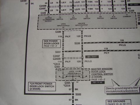
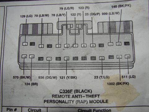
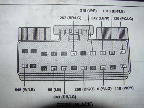
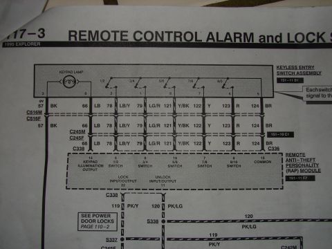
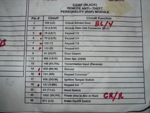
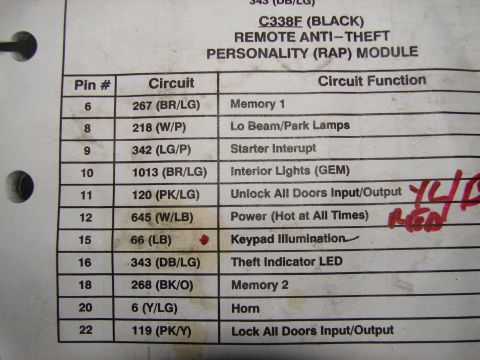
Wiring diagram for power door locks showing RAP module connections, splices and the master window/door lock control switch.
Part of 1972-1976 Ford Ranchero Wiring Diagrams
This is one page of a factory-style Ford wiring diagram covering the power door lock / keyless entry keypad circuit. It shows a module (top, dashed box) with pin assignments: pin 15 Keypad Illumination Output, pin 5 (1/2 switch), pin 6 (3/4 switch), pin 19 (5/6 switch), pin 7 (7/8 switch), pin 8 (9/10 switch), pin 15 Common, pin 22 Lock Input/Output, and pin 11 Unlock Input/Output. Circuit wires are identified by number and color: 66 LB, 78 LB/Y, 79 LG/R, 121 Y/BK, 122 Y, 123 R, 124 BR, 119 PK/Y, 120 PK/LG, and 57 BK (ground). Connectors and splices shown include C516F, C245M, C245F, C338, C336, C501, *C514, S337, S338, and S500. The lower dashed box is the Master Window/Door Lock Control Switch (4 door), with a note that a 2-door uses the LH Front Power Door Lock Switch (*C514). A callout explains the switch directs a ground signal to the RAP module to lock/unlock doors. Cross-references point to Power Door Locks page 110-2, grounds on pages 10-9 and 10-11, and grid locations 151-10 C1 and 151-11 A2.
Is this accurate? Sign in to help verify it.
Frequently asked questions
- What wire colors are used for the lock and unlock circuits at the master window/door lock control switch?
- Circuit 119 is PK/Y (pink/yellow) and circuit 120 is PK/LG (pink/light green), running through connectors C338, C245F/C245M, and C501 (*C514 on 2-door).
- What does the master window/door lock control switch actually do in this circuit?
- Per the callout, it directs a ground signal to the RAP module to lock or unlock the doors. Its pin 4 carries 0V on circuit 57 BK to ground splice S500.
- Which module pins connect to the keypad switches?
- Pin 5 is the 1/2 switch, pin 6 the 3/4 switch, pin 19 the 5/6 switch, pin 7 the 7/8 switch, pin 8 the 9/10 switch, pin 15 is Common and also Keypad Illumination Output, pin 22 is Lock Input/Output, and pin 11 is Unlock Input/Output.
- Where can I find more detail on the power door locks and grounds in this manual?
- The diagram references 'See Power Door Locks page 110-2' and 'See Grounds pages 10-9, 10-11', plus grid references 151-10 C1 and 151-11 A2.
- What is different for 2-door versus 4-door vehicles in this diagram?
- Connector *C514 and the LH Front Power Door Lock Switch apply to 2-door vehicles, while C501 and the Master Window/Door Lock Control Switch apply to 4-door vehicles.
No comments yet.