Ford C338F Black 22-Pin Connector Pinout - Circuit Numbers & Wire Colors
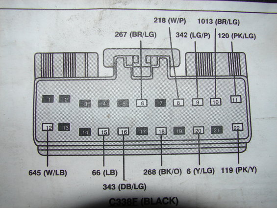
Connector C338F pinout diagram showing numbered terminals with wire colors such as W/P, BR/LG, LB and PK/Y.
This scan shows a connector face/pinout diagram for Ford connector C338F, identified as a BLACK 22-cavity connector arranged in two rows (pins 1-11 across the top, pins 12-22 across the bottom). Leader lines identify the circuit number and wire color code for each populated cavity: pin 6 = circuit 267 (Brown/Light Green), pin 8 = 218 (White/Purple), pin 9 = 342 (Light Green/Purple), pin 10 = 1013 (Brown/Light Green), pin 11 = 120 (Pink/Light Green), pin 12 = 645 (White/Light Blue), pin 15 = 66 (Light Blue), pin 16 = 343 (Dark Blue/Light Green), pin 18 = 268 (Black/Orange), pin 20 = 6 (Yellow/Light Green), and pin 22 = 119 (Pink/Yellow). The remaining cavities (1-5, 7, 13, 14, 17, 19, 21) are shown shaded with no circuit callouts, indicating they are unused or not detailed in this view. A reader can use this page to identify which wire lands in which cavity of C338F when diagnosing, back-probing, or repairing this harness connector. The page carries no year, model, or system caption beyond the connector ID, so applicability must be inferred from the accompanying pages or the service manual it came from.
Is this accurate? Sign in to help verify it.
Frequently asked questions
- What connector does this diagram show?
- It shows connector C338F, labeled BLACK, a 22-cavity connector with pins 1-11 in the top row and 12-22 in the bottom row.
- What circuit and wire color is at pin 22 of C338F?
- Pin 22 carries circuit 119 with a Pink/Yellow (PK/Y) wire.
- Which pins of C338F have circuits identified in this diagram?
- Pins 6 (267 BR/LG), 8 (218 W/P), 9 (342 LG/P), 10 (1013 BR/LG), 11 (120 PK/LG), 12 (645 W/LB), 15 (66 LB), 16 (343 DB/LG), 18 (268 BK/O), 20 (6 Y/LG), and 22 (119 PK/Y).
- What wire color is circuit 218 at this connector?
- Circuit 218 is shown as W/P (White/Purple) at pin 8.
- Are all 22 cavities used?
- No. Pins 1-5, 7, 13, 14, 17, 19, and 21 are shown shaded with no circuit callouts, indicating they are unused or not detailed here.
Comments
More from this build
No comments yet.