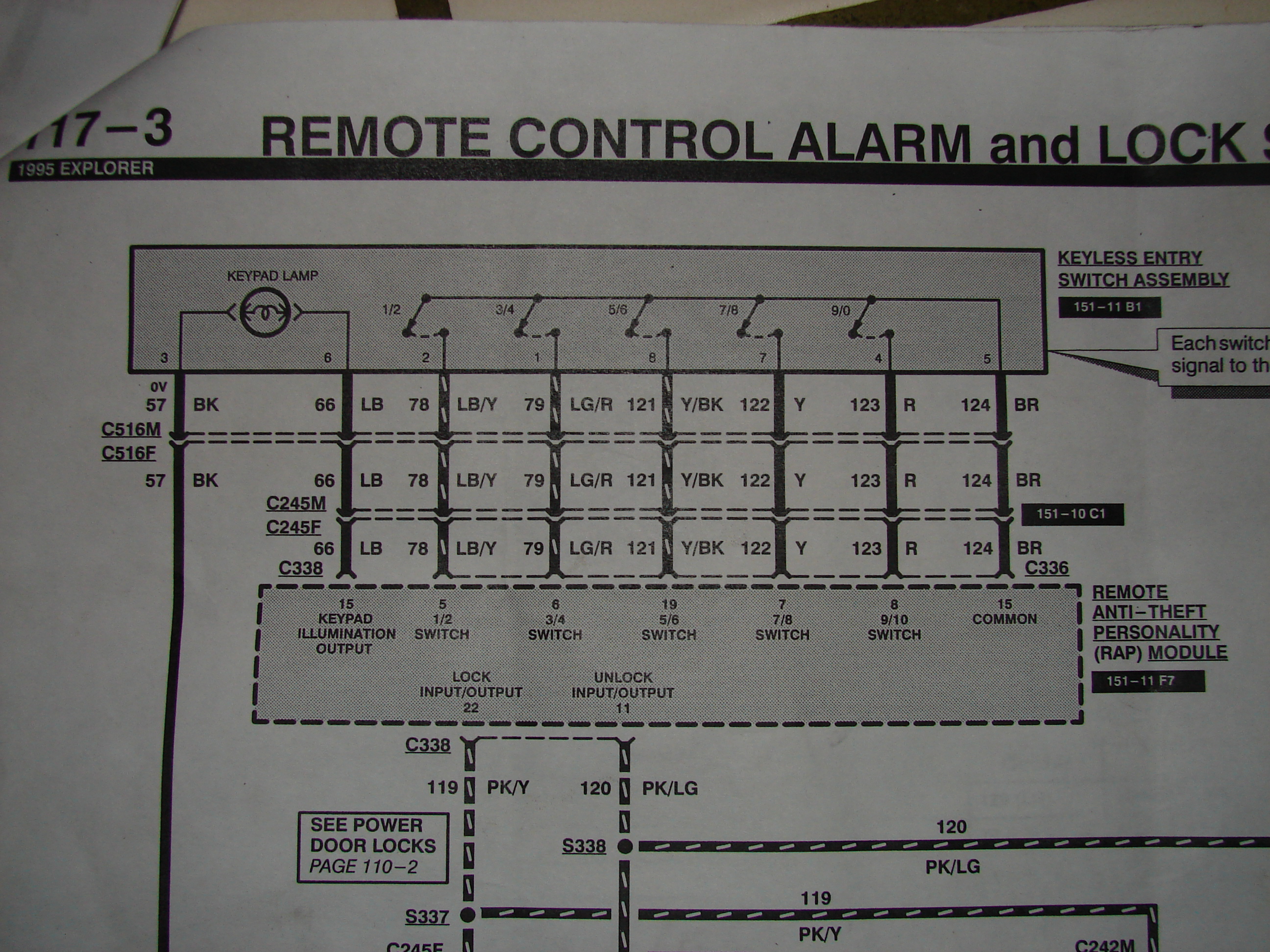
1995 Ford Explorer Keyless Entry & RAP Module Wiring Diagram (Page 117-3)
Reference · 1972-1976 RancheroAll 12 wiring diagrams
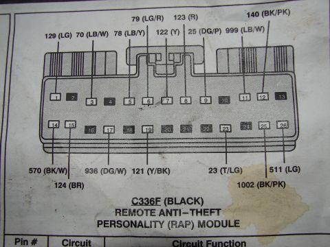
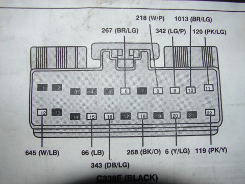
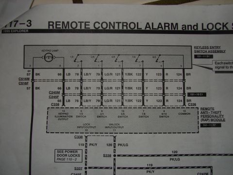
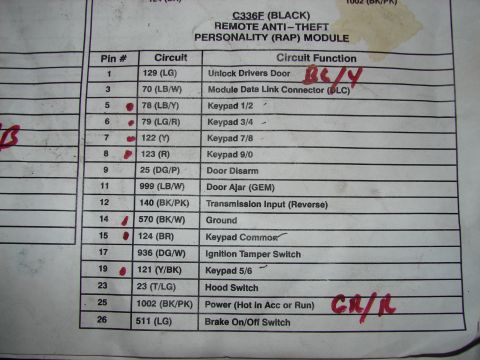
Wiring diagram for a 1995 Explorer remote control alarm and lock system showing keypad, RAP module and color-coded circuits.
Part of 1972-1976 Ford Ranchero Wiring Diagrams
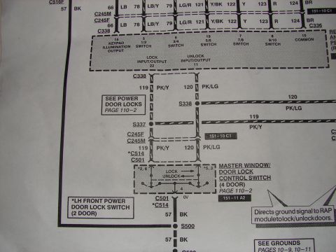
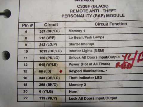
This is a scanned page (117-3) from the 1995 Ford Explorer factory wiring diagram set, covering the "Remote Control Alarm and Lock" system (title partially cut off at the right edge). It diagrams the Keyless Entry Switch Assembly (grid reference 151-11 B1), including the keypad lamp and the five keypad switches (1/2, 3/4, 5/6, 7/8, 9/0), and shows how they connect through connectors C516M/C516F, C245M/C245F, C338, and C336 to the Remote Anti-Theft Personality (RAP) Module (grid reference 151-11 F7). Circuit numbers and wire colors are given for each switch line: 57 BK, 66 LB, 78 LB/Y, 79 LG/R, 121 Y/BK, 122 Y, 123 R, 124 BR. RAP module pin functions are labeled: keypad illumination output (pin 15), 1/2 switch (5), 3/4 switch (6), 5/6 switch (19), 7/8 switch (7), 9/10 switch (8), common (15), lock input/output (22), and unlock input/output (11). Lock/unlock circuits 119 PK/Y and 120 PK/LG run through splices S337 and S338, with a cross-reference to Power Door Locks on page 110-2. A reader can trace keypad keyless-entry wiring, pinouts, and wire colors for diagnosing the RAP system.
This document covers 1995, which may differ from this 1973 Ford Ranchero.
Is this accurate? Sign in to help verify it.
Frequently asked questions
- What wire colors connect the keyless entry keypad to the RAP module on a 1995 Explorer?
- The diagram shows circuits 57 BK (black), 66 LB (light blue), 78 LB/Y, 79 LG/R, 121 Y/BK, 122 Y, 123 R, and 124 BR running from the keyless entry switch assembly through connectors C516, C245, and C338/C336 to the RAP module.
- Which RAP module pins handle the keypad switches?
- Pin 5 is the 1/2 switch, pin 6 the 3/4 switch, pin 19 the 5/6 switch, pin 7 the 7/8 switch, pin 8 the 9/10 switch, pin 15 serves as keypad illumination output and common, pin 22 is lock input/output, and pin 11 is unlock input/output.
- What are the lock and unlock circuit wires from the RAP module?
- Circuit 119 PK/Y (lock) and circuit 120 PK/LG (unlock) leave the RAP module through connector C338 and pass through splices S337 and S338; the diagram refers to Power Door Locks on page 110-2 for continuation.
- Which connectors are in the keypad-to-RAP-module circuit?
- The wiring passes through connector pair C516M/C516F, connector pair C245M/C245F, and connectors C338 and C336 before reaching the RAP module.
- What vehicle does this wiring diagram apply to?
- The page header states "1995 EXPLORER," page 117-3, for the Remote Control Alarm and Lock system.



No comments yet.