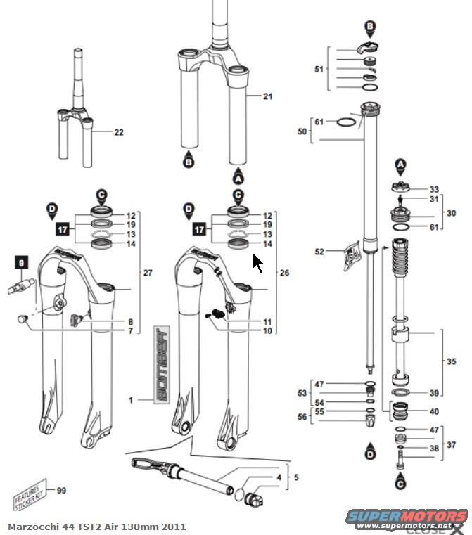
Marzocchi 44 TST2 Air 130mm 2011 Fork Exploded Parts Diagram
Reference · 1992-1996 F-150All 4 exploded parts diagrams
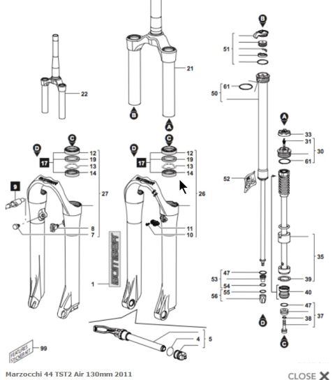
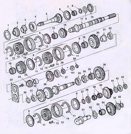
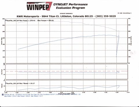
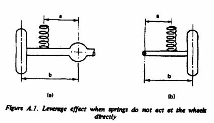
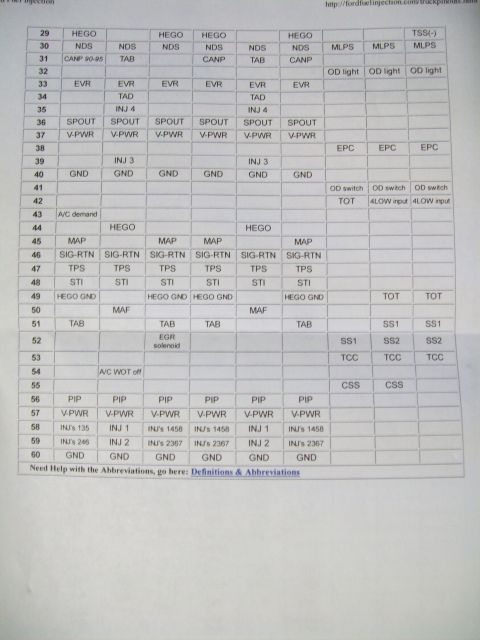
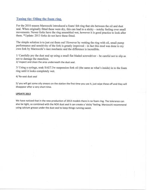
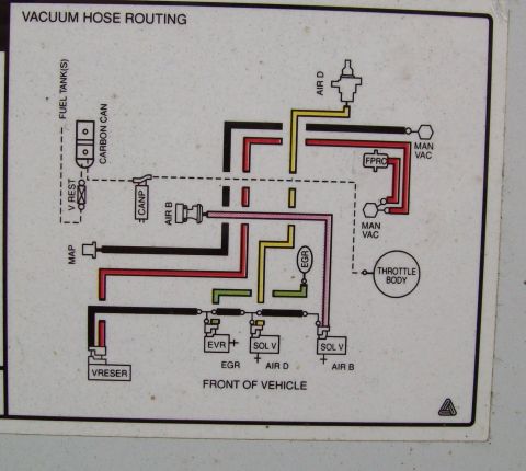

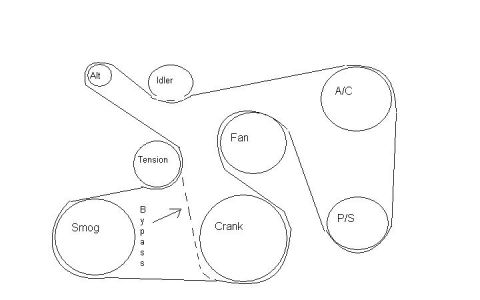
Exploded parts breakdown drawing of a Marzocchi 44 TST2 Air 130mm fork showing numbered assembly components.
Part of 1992-1996 Ford F-150 Exploded Parts Diagrams
This document is an exploded parts diagram for the Marzocchi 44 TST2 Air 130mm suspension fork, model year 2011. It is a bicycle (mountain bike) front fork diagram, not an automotive document. The illustration breaks the fork into its major assemblies: the crown/steerer units (items 21 and 22), left and right lower leg/slider assemblies (items 26 and 27), the air/damper cartridge stack (items 50, 51, 30, 33, 31, 61), the spring/shaft assembly (item 35) with associated seals (39, 40, 47), and foot hardware groups (37, 53, 54, 55, 56, 38). Seal kits for each lower leg are grouped under item 17, consisting of dust seal (12), retaining ring (19), oil seal (13), and bushing/ring (14). The thru-axle with quick-release is item 5 with cap 4, and decal kits are items 1 (Bomber logo) and 99 (features sticker kit). Letter markers A, B, C, and D cross-reference where sub-assemblies install into the main structure. A reader can use this diagram to identify individual replacement part callout numbers for ordering service parts and to understand the assembly order of the fork's internals.
This document covers 2011, which may differ from this 1993 Ford F-150.
Is this accurate? Sign in to help verify it.
Frequently asked questions
- What fork does this exploded diagram cover?
- The Marzocchi 44 TST2 Air 130mm, model year 2011, as stated in the caption at the bottom of the diagram.
- What parts make up the seal kit group (item 17) in the lower legs?
- Item 17 groups four parts shown for each lower leg: 12 (dust seal), 19 (retaining ring/washer), 13 (oil seal), and 14 (lower ring/bushing).
- Which callout number identifies the axle assembly?
- Item 5 is the grouped axle assembly with quick-release lever, and item 4 is the round cap/plug shown beside it.
- What do the letter markers A, B, C, and D indicate?
- They are cross-reference markers showing where sub-assemblies (such as the cartridge, seal groups, and foot hardware) install into the crown/steerer and lower leg assemblies.
- What decal items are shown in the diagram?
- Item 1 is the Bomber logo decal sheet and item 99 is labeled 'Features Sticker Kit'.
No comments yet.