Home/
Registry/
Ford/
Bronco/
1992-1996/
1996 Ford Bronco/
Photo
supermotors.net/registry/media/1155558
1994 Ford Bronco/F-150/Econoline Anti-Theft Alarm Diagnosis Test M (13-11-22)
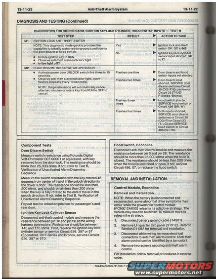
Ford service manual anti-theft alarm diagnostics: door-disarm/hood-switch test steps, flash-count interpretation, plus door disarm switch resistance specs (more than 25,000 ohms open, less than 200 ohms closed).
This is page 13-11-22 from the 1994 Ford Econoline / F-150 / F-250 / F-350 / Bronco / F-Super Duty Body/Chassis service manual, covering the Anti-Theft Alarm System (Diagnosis and Testing, continued). The main table presents Test M — diagnostics for door disarm, ignition keylock cylinder, and hood switch inputs — with steps M1 (Ignition Lock Anti-Theft Switch) and M2 (Door Disarm, Hood Switch Operation). It explains how to enter diagnostic mode, interpret anti-theft indicator flash counts (one to four flashes), and which circuits to service: Circuit 25 (DG/P) Econoline or Circuit 23 (T/LG) F-Series/Bronco for door disarm, and Circuit 486 (BR/W) for the hood switch. Component test procedures follow: Door Disarm Switch resistance checks (>25,000 ohms with key removed, <200 ohms rotated 45 degrees toward unlock) using Rotunda Digital Volt-Ohmmeter 007-00001; Ignition Key Lock Cylinder Sensor (145–175 ohms between pins 10 and 26, servicing Circuits 936, 397, 57, or 570); and Hood Switch, Econoline (pins 5 and 26, >25,000 ohms closed, <200 ohms open). The page ends with removal and installation steps for the Econoline anti-theft control module, including battery disconnection, quarter trim panel removal (31012), and a PCM (12A650) adaptive strategy relearn note.
Is this accurate? Sign in to help verify it.
Frequently asked questions
- What does it mean if the anti-theft alarm indicator flashes two times during Test M2?
- Two flashes mean the door disarm input is shorted. Service the door disarm switches: Circuit 25 (DG/P) on Econoline or Circuit 23 (T/LG) on F-Series/Bronco.
- What resistance should the ignition key lock cylinder sensor read?
- With the anti-theft control module disconnected, resistance between pin 10 and pin 26 at the wiring harness connectors should be 145–175 ohms. If not, replace the sensor or service Circuit 936, 397 or 57 (Econoline); on F-Series and Bronco, service Circuits 936, 397 or 570.
- How do I test the door disarm switch resistance?
- Using a Rotunda Digital Volt-Ohmmeter 007-00001 or equivalent, resistance should be more than 25,000 ohms with the key removed, and less than 200 ohms with the key rotated 45 degrees toward unlock (remaining under 200 ohms to end of travel). Repeat for passenger's and rear doors.
- What flash count indicates the hood switch is shorted?
- Three flashes indicate the hood switch is shorted. Service the hood switch or Circuit 486 (BR/W).
- How is the Econoline anti-theft control module removed?
- Disconnect the battery ground cable (14301), remove the LH quarter trim panel (31012) per Section 01-05A, disconnect the white wiring harness connectors (the anti-theft control is tan), and remove the two securing screws. Install in reverse order.
Comments
More from this build


No comments yet.