Home/
Registry/
Ford/
Bronco/
1992-1996/
1996 Ford Bronco/
Photo
supermotors.net/registry/media/1167005
Ford E4OD Solenoid Body Pin ID, Resistance Chart & PCM Pins - ATSG Fig. 16

Reference · 1992-1996 BroncoAll 103 data & spec plates
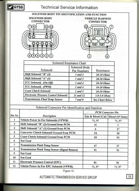

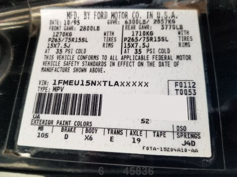
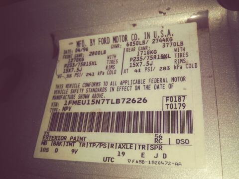
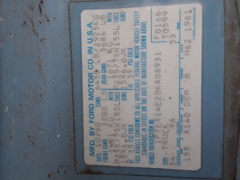
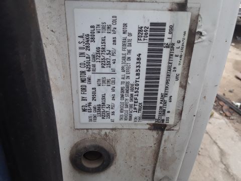
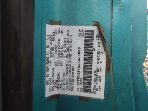





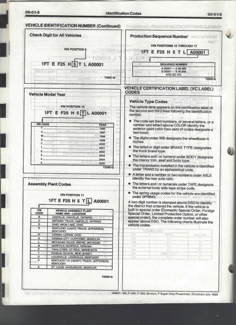
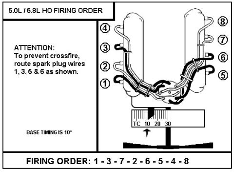
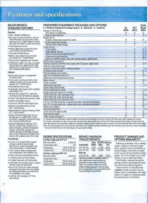



ATSG transmission solenoid connector pinout and resistance chart: shift/TCC/coast-clutch solenoids 20-30 ohms, EPC solenoid 3.0-5.0 ohms, with gas and diesel PCM pin assignments.
Part of 1992-1996 Ford Bronco Data & Spec Plates
This page (page 13, Figure 16) from an ATSG (Automatic Transmission Service Group) Technical Service Information manual covers solenoid body pin identification and function, uploaded as a reference for a Ford E4OD automatic transmission. It shows two connector diagrams: the 12-pin solenoid body connector and the mating vehicle harness connector, with pin numbering for each. A Solenoid Resistance Chart lists the pin pairs and expected resistance values for each component: Shift Solenoids A and B (20-30 ohms), TCC on-off solenoid (20-30 ohms), TCC PWM solenoid (10-20 ohms), Coast Clutch Solenoid (20-30 ohms), Electronic Pressure Control solenoid (3.0-5.0 ohms), and the Transmission Fluid Temp Sensor (pins 7 and 8, see separate chart). A second table maps each of the 12 solenoid connector pins to its function and the corresponding PCM connector pin, with separate columns for Gas & Diesel (Cal) and Diesel (49 State) applications. Pins 1 and 12 carry vehicle power (VPWR, PCM pins 71 and 97); grounds from the PCM control the shift, converter clutch, and coast clutch solenoids; pins 6, 9, and 10 are not used. This document is useful for diagnosing solenoid circuits with an ohmmeter and tracing wiring to the PCM.
Is this accurate? Sign in to help verify it.
Frequently asked questions
- What resistance should E4OD shift solenoids A and B read?
- Per the Solenoid Resistance Chart, Shift Solenoid "B" (2) is measured across pins 1 and 2, and Shift Solenoid "A" (1) across pins 1 and 3; both should read 20-30 ohms.
- What is the resistance spec for the Electronic Pressure Control (EPC) solenoid?
- The EPC solenoid is measured across solenoid body pins 11 and 12 and should read 3.0-5.0 ohms.
- Which pins are used for the transmission fluid temperature sensor?
- The Transmission Fluid Temp Sensor uses solenoid body pins 7 and 8; pin 7 goes to PCM pin 37 and pin 8 (Signal Return) to PCM pin 91. Resistance values are 'See Chart Below' (on a separate chart).
- What is the difference between the TCC on-off and PWM solenoid resistance?
- Both are measured across pins 1 and 4, but the TCC on-off solenoid should read 20-30 ohms while the TCC PWM solenoid should read 10-20 ohms.
- Which solenoid connector pins are not used?
- Pins 6, 9, and 10 are listed as Not Used in the Solenoid Connector Pin Identification and Function table.






No comments yet.