Home/
Registry/
Ford/
Bronco/
1992-1996/
1996 Ford Bronco/
Photo
supermotors.net/registry/media/1167004
1994 Ford Bronco/F-Series C103 & C108 Connector Pinouts - EVTM Page 150-2

Reference · 1992-1996 BroncoAll 411 wiring diagrams

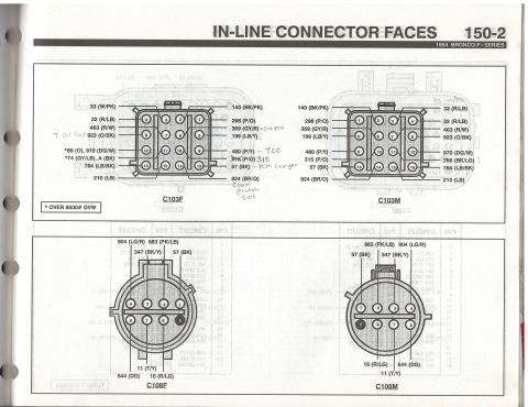
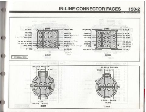
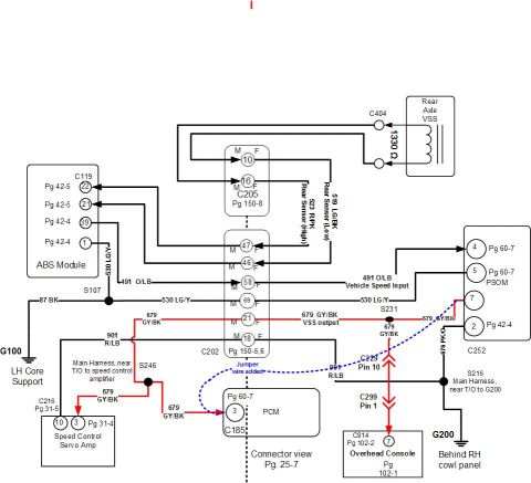
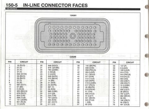
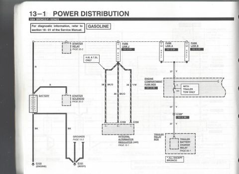
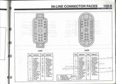
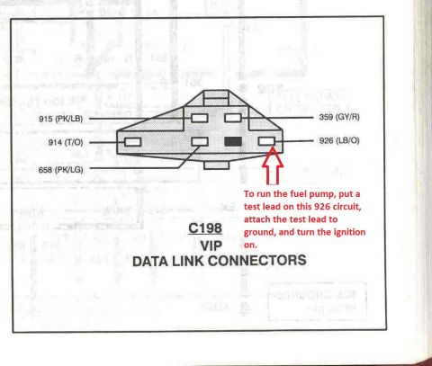
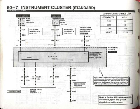





Ford in-line connector face diagrams for C103F, C103M, C108F and C108M with color-coded circuit identification.
Part of 1992-1996 Ford Bronco Wiring Diagrams
This is page 150-2 ("In-Line Connector Faces") from the 1994 Ford Bronco/F-Series Electrical and Vacuum Troubleshooting Manual (EVTM). It shows pinout face diagrams for two in-line harness connector pairs: C103 (female C103F and male C103M, 16-cavity rectangular connectors) and C108 (female C108F and male C108M, 8-cavity round connectors). Each cavity is numbered and labeled with its circuit number and wire color code, for C103: circuits such as 33 (W/PK), 32 (R/LB), 463 (R/W), 923 (O/BK), 970 (DG/W), 784 (LB/BK), 210 (LB), 140 (BK/PK), 298 (P/O), 359 (GY/R), 199 (LB/Y), 480 (P/Y), 315/915 (P/O), 57 (BK), 924 (BR/O), plus *89 (O) and *74 (GY/LB) which apply to vehicles over 8500 lb GVW. C108 carries circuits 904 (LG/R), 883 (PK/LB), 347 (BK/Y), 57 (BK), 11 (T/Y), 644 (DG), and 16 (R/LG). Handwritten annotations identify several circuit functions: 923 as transmission oil temperature, 359 as signal return, 480 as TCC, 57 as PCM case ground, and 924 as coast clutch solenoid. A reader can use this page to identify wires and pin positions when testing or repairing these harness connectors.
Is this accurate? Sign in to help verify it.
Frequently asked questions
- What connectors are shown on page 150-2 of the 1994 Bronco/F-Series EVTM?
- It shows the in-line connector faces for C103 (female C103F and male C103M, 16-pin) and C108 (female C108F and male C108M, 8-pin), with circuit numbers and wire colors for each pin.
- What wire circuits pass through connector C103?
- Circuits 33 (W/PK), 32 (R/LB), 463 (R/W), 923 (O/BK), 970 (DG/W), 784 (LB/BK), 210 (LB), 140 (BK/PK), 298 (P/O), 359 (GY/R), 199 (LB/Y), 480 (P/Y), 315 (P/O), 57 (BK), and 924 (BR/O), plus *89 (O) and *74 (GY/LB)/A (BK) on vehicles over 8500# GVW.
- What do the handwritten notes on the C103F diagram identify?
- They label circuit 923 (O/BK) as transmission oil temp, 359 (GY/R) as signal return, 480 (P/Y) as TCC, 57 (BK) as PCM case ground, and 924 (BR/O) as coast clutch solenoid. The printed 915 (P/O) is corrected by hand to 315.
- Which circuits are in connector C108?
- C108 (both F and M halves) carries circuits 904 (LG/R), 883 (PK/LB), 347 (BK/Y), 57 (BK), 11 (T/Y), 644 (DG), and 16 (R/LG).
- What does the asterisk (*) mean on some C103 circuits?
- Per the legend, asterisked circuits (*89 (O) and *74 (GY/LB)) apply to vehicles over 8500# GVW.






No comments yet.