Home/
Registry/
Ford/
Bronco/
1992-1996/
1996 Ford Bronco/
Photo
supermotors.net/registry/media/1168665
1996 Ford Bronco C202F 76-Pin Connector Pinout - EVTM Page 150-4

Reference · 1992-1996 BroncoAll 411 wiring diagrams




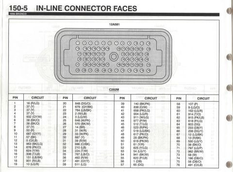
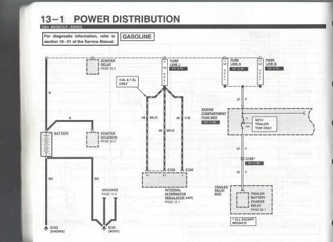
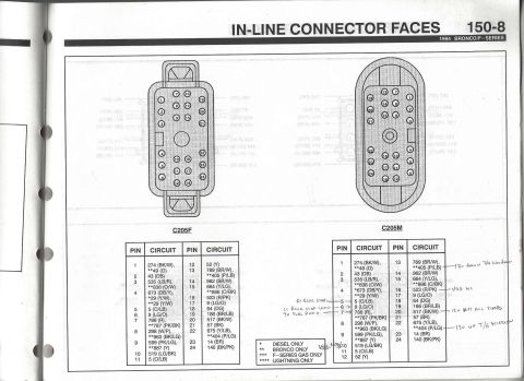
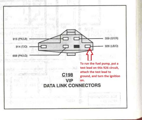

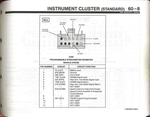
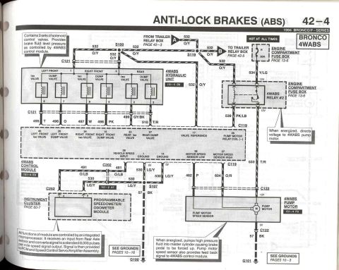
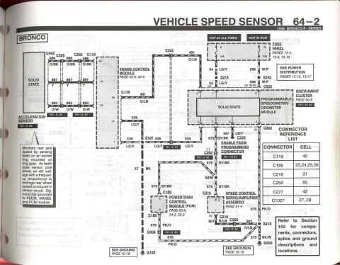



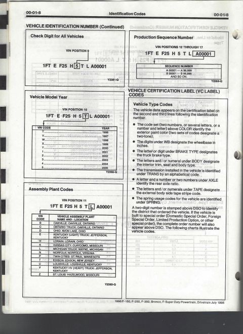



Service-manual connector-face chart (C202F, page 150-4) listing each pin and its color-coded circuit for a 1996 Bronco.
Part of 1992-1996 Ford Bronco Wiring Diagrams
This is page 150-4 of the 1996 Ford Bronco Electrical & Vacuum Troubleshooting Manual (EVTM), titled "In-Line Connector Faces." It documents connector C202F (part reference 14401), a 76-pin in-line bulkhead connector, showing a face-view illustration with the numbered pin cavity layout arranged in six rows. Below the illustration, a four-column table lists every pin (1 through 76) with its assigned circuit number and wire color code, for example pin 1 = circuit 16 (R/LG), pin 9 = 50 (R), pin 27 = 14 (BR), pin 50 = 619 (PK/W), pin 52 = 625 (Y/LG), and pin 76 = 491 (O/LB). A footnote indicates circuit 54 (LG/Y) at pin 53 applies to vehicles without remote/keyless entry. The previous owner has hand-annotated pins 50 and 52, circling them and noting they are the left crash sensor feed and left crash sensor feed monitor circuits (airbag system). This page lets a reader identify which circuit and wire color is present at any cavity of the C202F connector when tracing or repairing wiring on a 1996 Bronco. It pairs with page 150-5, which covers the mating connector C202M.
Is this accurate? Sign in to help verify it.
Frequently asked questions
- What connector does EVTM page 150-4 for the 1996 Bronco show?
- It shows the face view and complete pinout of in-line connector C202F (labeled 14401), a 76-pin connector, with a table of circuit numbers and wire colors for every pin.
- What circuit is on pin 50 of the 1996 Bronco C202F connector?
- Pin 50 is circuit 619 (PK/W). A handwritten note on this scan identifies it as the left crash sensor feed.
- What does the asterisk (*) next to circuit 54 (LG/Y) mean?
- The asterisk indicates 'without remote/keyless entry', that circuit at pin 53 applies only to vehicles not equipped with remote keyless entry.
- What wire color is circuit 16 on pin 1 of C202F?
- Pin 1 carries circuit 16 with wire color R/LG (red/light green).
- Which pin of C202F carries circuit 625 (Y/LG)?
- Pin 52 carries circuit 625 (Y/LG); a handwritten note identifies it as the left crash sensor feed monitor.






No comments yet.