Home/
Registry/
Ford/
Bronco/
1992-1996/
1996 Ford Bronco/
Photo
supermotors.net/registry/media/1166991
1994 Ford Bronco/F-Series EVTM 150-2: C103 & C108 In-Line Connector Pinouts

Reference · 1992-1996 BroncoAll 411 wiring diagrams

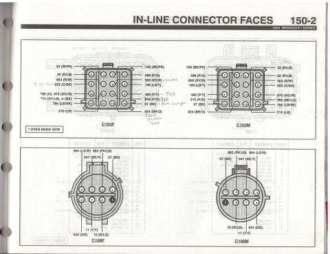
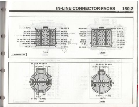
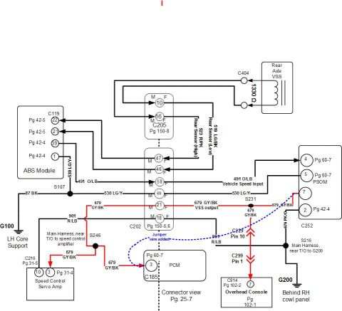
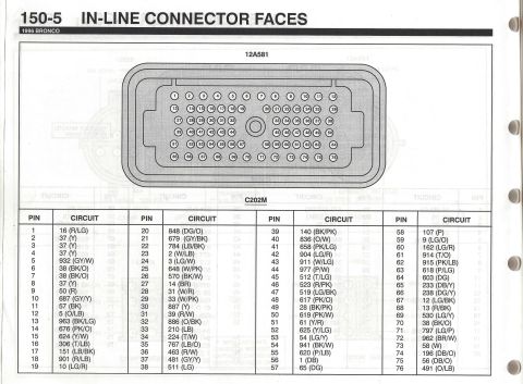
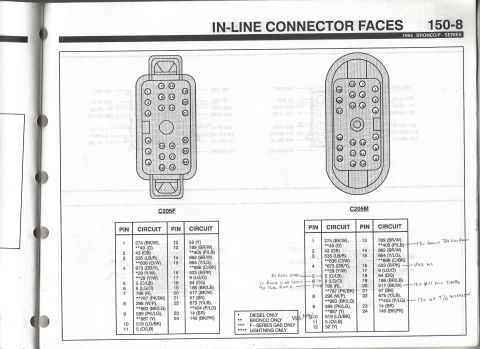
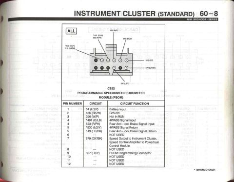
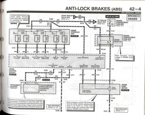
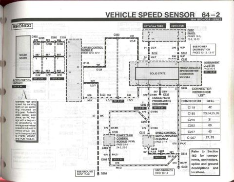


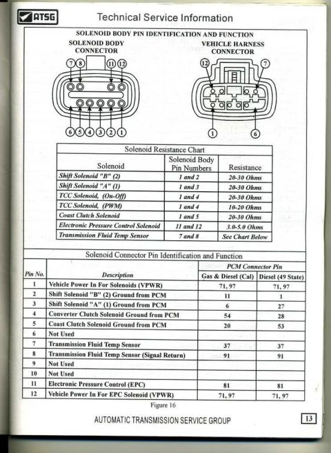



Ford in-line connector face diagrams for C103F, C103M, C108F and C108M with color-coded circuit identification.
Part of 1992-1996 Ford Bronco Wiring Diagrams
This is page 150-2, "In-Line Connector Faces," from the 1994 Ford Bronco/F-Series Electrical & Vacuum Troubleshooting Manual (EVTM). It shows pin-face diagrams for in-line connectors C103 (female C103F and male C103M, 16-pin rectangular) and C108 (female C108F and male C108M, 8-pin round). Each pin is identified by its circuit number and wire color code, for example, on C103: 33 (W/PK), 32 (R/LB), 463 (R/W), 923 (O/BK), 970 (DG/W), 784 (LB/BK), 210 (LB), 140 (BK/PK), 298 (P/O), 359 (GY/R), 199 (LB/Y), 480 (P/Y), 315 (P/O), 57 (BK), and 924 (BR/O). Circuits 89 (O) and 74 (GY/LB) are footnoted "* OVER 8500# GVW." C108 carries circuits 904 (LG/R), 883 (PK/LB), 347 (BK/Y), 57 (BK), 644 (DG), 11 (T/Y), and 16 (R/LG). Handwritten annotations by the previous owner identify functions: 923 as oil temp, 359 as signal return, 480 as TCC, 57 as PCM case ground, and 924 as coast clutch solenoid, plus a correction of 915 to 315. Useful for tracing PCM/transmission wiring at these harness junctions.
Is this accurate? Sign in to help verify it.
Frequently asked questions
- What connectors are shown on page 150-2 of the 1994 Bronco/F-Series EVTM?
- It shows the in-line connector faces for C103 (female C103F and male C103M, 16-pin) and C108 (female C108F and male C108M, 8-pin), with circuit numbers and wire colors for each pin.
- What circuits pass through connector C103 on a 1994 Bronco/F-Series?
- Circuits 33 (W/PK), 32 (R/LB), 463 (R/W), 923 (O/BK), 970 (DG/W), 784 (LB/BK), 210 (LB), 140 (BK/PK), 298 (P/O), 359 (GY/R), 199 (LB/Y), 480 (P/Y), 315 (P/O), 57 (BK), and 924 (BR/O). Circuits 89 (O) and 74 (GY/LB)/A (BK) apply only to trucks over 8500# GVW.
- What wires are in connector C108?
- C108 is an 8-pin round connector carrying circuits 904 (LG/R), 883 (PK/LB), 347 (BK/Y), 57 (BK), 644 (DG), 11 (T/Y), and 16 (R/LG).
- What do the handwritten notes on this page identify?
- Handwritten notes mark circuit 923 as oil temp, 359 as signal return, 480 as TCC, 57 as PCM case ground, 924 as coast clutch solenoid, correct '915' to '315', and question circuit 766 (BK/LG) on C103M.
- What does the asterisk (*) mean on circuits 89 and 74?
- The footnote states '* OVER 8500# GVW', those circuits apply only to vehicles over 8500 lb gross vehicle weight.






No comments yet.