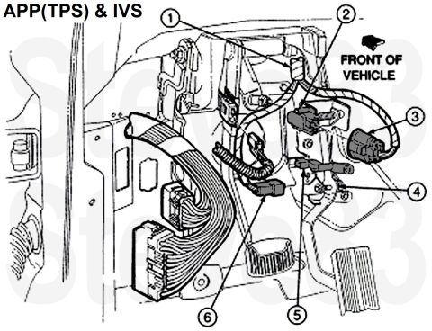
APP (TPS) and IVS sensor location diagram with numbered callouts…

Reference · 1992-1997 F-250All 5 wiring diagrams
'94.5-97 PowerStroke 7.3L DI Turbo Diesel Accelerator Pedal Position (APP) sensor & Idle Validation Switch (IVS) Pedal Assembly F6TZ9F836AA or on Amazon
IF THE IMAGE IS TOO SMALL, click it.
1 - Takeout from main wiring harness
2 - Accelerator Pedal Position sensor
3 - Connector for APP
4 - Accelerator pedal assembly
5 - Idle Validation Switch
6 - Connector for IVS
The IVS should be closed (less than 5 Ohms, short circuit, ON) when the pedal is released, and open (greater than 10K Ohms, OFF) at any other pedal position.
The APP is tested as this page describes:
Part of 1992-1997 Ford F-250 Wiring Diagrams
Is this accurate? Sign in to help verify it.
No comments yet.