Home/
Registry/
Ford/
Mustang/
1964-1973/
“Race Car Tope”/
Photo
supermotors.net/registry/media/1161885
Ford Experimental Aluminum V8 Cylinder Head Gasket Design - O-Ring Seal, Fig 23-24
Reference · 1964-1973 MustangAll 16 manual pages
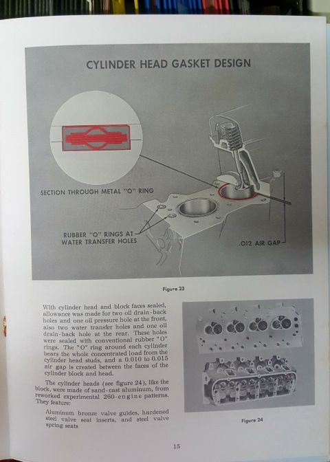
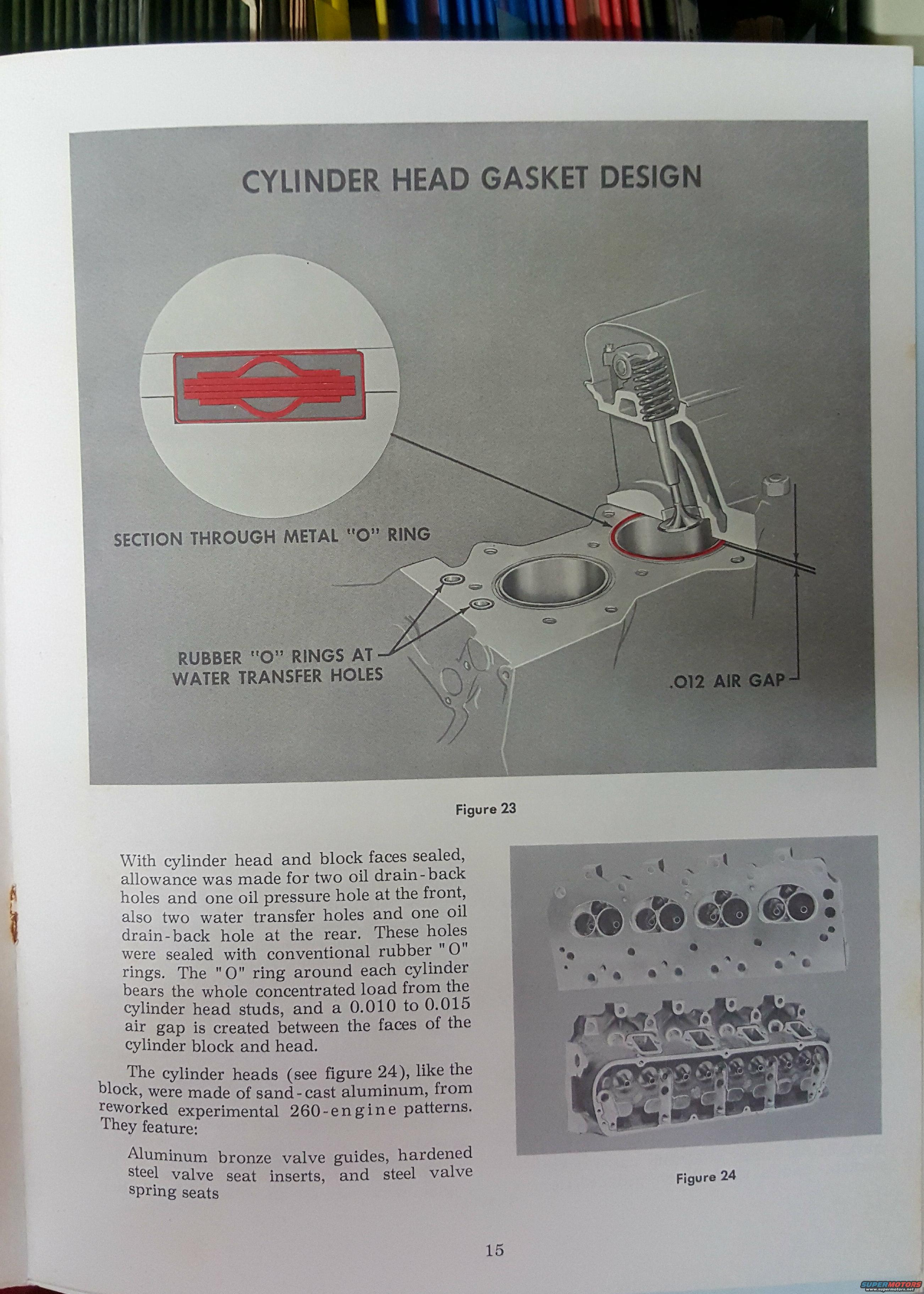
Manual page describing cylinder head gasket design with a sectioned metal O-ring figure and photographs of the cylinder heads.
Part of 1964-1973 Ford Mustang Manual Pages
This is page 15 of a Ford engineering/technical publication describing an experimental engine's cylinder head gasket design. The large illustration (Figure 23) shows a cutaway of the head-to-block sealing arrangement, with callouts identifying a section through the metal "O" ring that seals each cylinder bore, rubber "O" rings at the water transfer holes, and a .012-inch air gap between the head and block faces. The accompanying text explains that sealing allowance was made for two oil drain-back holes and one oil pressure hole at the front, plus two water transfer holes and one oil drain-back hole at the rear, all sealed with conventional rubber "O" rings. The metal "O" ring around each cylinder carries the full concentrated load from the cylinder head studs, creating a 0.010 to 0.015-inch air gap between the block and head faces. The text further notes that the cylinder heads (shown in the Figure 24 photographs) were sand-cast aluminum made from reworked experimental 260-engine patterns, featuring aluminum bronze valve guides, hardened steel valve seat inserts, and steel valve spring seats. Readers learn how this experimental gasketless O-ring sealing system worked and the construction details of the aluminum cylinder heads.
Is this accurate? Sign in to help verify it.
Frequently asked questions
- How were the cylinders sealed on this experimental Ford engine?
- Each cylinder was sealed with a metal "O" ring that bears the whole concentrated load from the cylinder head studs, creating a 0.010 to 0.015 inch air gap between the faces of the cylinder block and head.
- How were the oil and water passages sealed between the head and block?
- Two oil drain-back holes and one oil pressure hole at the front, plus two water transfer holes and one oil drain-back hole at the rear, were sealed with conventional rubber "O" rings.
- What were the cylinder heads made of?
- The cylinder heads, like the block, were sand-cast aluminum made from reworked experimental 260-engine patterns.
- What valve hardware features did the aluminum heads have?
- Aluminum bronze valve guides, hardened steel valve seat inserts, and steel valve spring seats.
- What air gap is called out in Figure 23?
- A .012 inch air gap between the cylinder block and head faces (the text states a range of 0.010 to 0.015 inch).



No comments yet.