Home/
Registry/
Ford/
Mustang/
1964-1973/
“Race Car Tope”/
Photo
supermotors.net/registry/media/1161888
Ford Mustang I Concept & Design - Mid-Engine Prototype Specs, Frame & Driveline
Reference · 1964-1973 MustangAll 16 manual pages
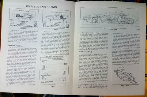
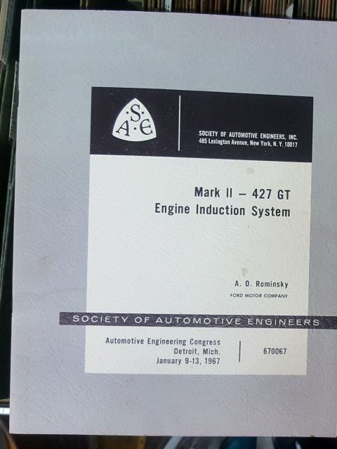
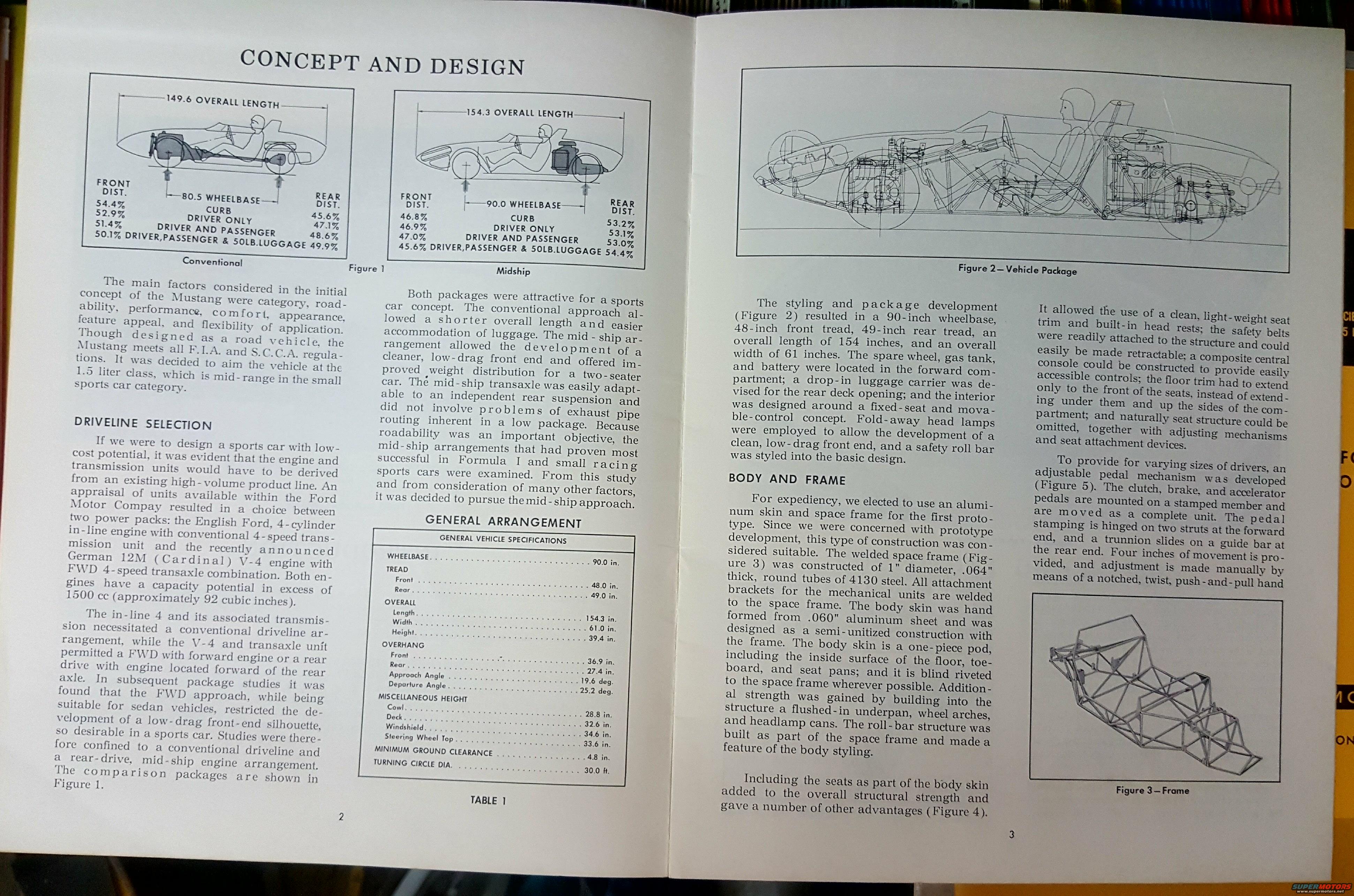
Manual page on vehicle concept and design with package layout drawings, frame illustration, and a general specifications table.
Part of 1964-1973 Ford Mustang Manual Pages
This two-page spread, titled "Concept and Design," is from an engineering paper describing the original Ford Mustang two-seat sports car concept (the mid-engine Mustang I prototype). It explains the initial design goals, category, roadability, performance, comfort, appearance, and states the car meets F.I.A. and S.C.C.A. regulations and targets the 1.5-liter class. The Driveline Selection section compares the English Ford in-line 4-cylinder with conventional 4-speed transmission versus the German 12M (Cardinal) V-4 with FWD transaxle, and explains why a rear-drive mid-ship engine layout was chosen. Figure 1 compares conventional (149.6 in. overall, 80.5 in. wheelbase) and midship (154.3 in. overall, 90.0 in. wheelbase) packages with front/rear weight distribution percentages under various load conditions. Table 1 lists full vehicle specifications: 90.0 in. wheelbase, 48/49 in. front/rear tread, 154.3 x 61.0 x 39.4 in. overall dimensions, ground clearance 4.8 in., and 30 ft. turning circle. The Body and Frame section details the welded space frame of 1-inch.064-inch-wall 4130 steel tubing, hand-formed.060-inch aluminum body skin, integral roll bar, seats built into the body skin, and an adjustable pedal assembly with four inches of travel. Figures 2 and 3 show the vehicle package cutaway and the tubular frame.
Is this accurate? Sign in to help verify it.
Frequently asked questions
- What are the overall dimensions of the mid-ship Mustang concept?
- Per Table 1: wheelbase 90.0 in., overall length 154.3 in., width 61.0 in., height 39.4 in., front tread 48.0 in., rear tread 49.0 in., minimum ground clearance 4.8 in., turning circle 30.0 ft.
- What engines were considered for the Mustang concept's driveline?
- Two power packs from Ford's high-volume lines: the English Ford 4-cylinder in-line engine with conventional 4-speed transmission, and the German 12M (Cardinal) V-4 engine with FWD 4-speed transaxle. Both had capacity potential over 1500 cc (about 92 cubic inches).
- Why was the mid-ship engine layout chosen over the conventional layout?
- The mid-ship arrangement allowed a cleaner, low-drag front end, improved weight distribution for a two-seater, was easily adaptable to independent rear suspension, and avoided exhaust routing problems of a low package. It followed layouts proven in Formula I and small racing sports cars.
- How was the prototype's frame and body constructed?
- A welded space frame of 1" diameter, .064" thick round 4130 steel tubes, with a hand-formed .060" aluminum one-piece body skin blind-riveted to the frame as semi-unitized construction. The roll bar was built into the space frame.
- How did the fixed-seat design accommodate different drivers?
- An adjustable pedal mechanism was developed: clutch, brake, and accelerator pedals mount on a stamped member moved as a unit, with four inches of travel adjusted manually by a notched, twist, push-and-pull hand control.
No comments yet.