Home/
Registry/
Ford/
Mustang/
1964-1973/
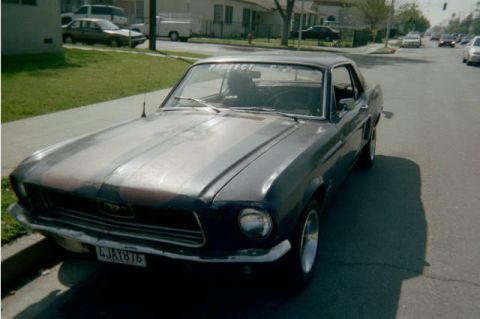
1965 Ford Mustang/
Photo
supermotors.net/registry/media/1007190
Electric Heat Air Handler Wiring Diagram B17576-02 - 208/230V Schematic & Notes

Reference · 1964-1973 MustangAll 10 wiring diagrams
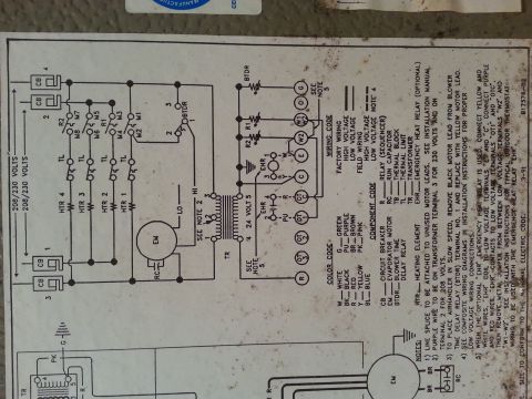
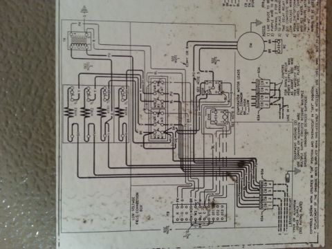
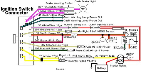
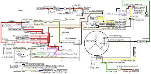
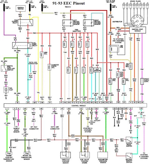
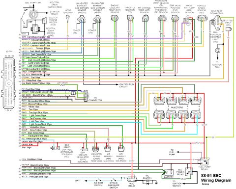
Wiring diagram on an HVAC unit with color-code and wiring-code legends, voltage circuits, relays and motor connections.
Part of 1964-1973 Ford Mustang Wiring Diagrams
This document is a factory wiring diagram label (drawing number B17576-02, dated 3-91) for an electric-heat air handler / HVAC unit operating on 208/230 volts, not an automotive diagram. The schematic shows up to four heating elements (HTR 1-4) protected by circuit breakers (CB) and thermal limits (TL), switched through sequencer relay contacts (M1-M8, R1, R2). It also depicts the evaporator blower motor (EM) with run capacitor (RC), high/low speed taps, a blower time delay relay (BTDR), a 24-volt control transformer (TR) with 208/230-volt primary taps, and low-voltage thermostat terminals (R, OT3, OT2, OT1, OTC, C, E, W2, W1/W2, O, G). Legends include a wire color code (White, Black, Red, Yellow, Blue, Green, Purple, Brown, Pink), a component code, and a wiring code distinguishing factory and field wiring at high and low voltage. Five installation notes cover splicing unused motor leads, selecting transformer terminal 3 for 230 V or terminal 2 for 208 V, converting the blower to slow speed by swapping the black lead for the yellow lead at BTDR terminal 1, referencing composite low-voltage wiring diagrams, and wiring the optional Emergency Heat Relay (EHR) with an outdoor thermostat. Field wiring must conform to the National Electric Code.
This document covers 1991, which may differ from this 1965 Ford Mustang.
Is this accurate? Sign in to help verify it.
Frequently asked questions
- Which transformer terminal is used for 230-volt versus 208-volt operation?
- Note 2 states the purple wire goes on transformer terminal 3 for 230 volts and on terminal 2 for 208 volts.
- How do you set the air handler blower to slow speed?
- Per note 3, remove the black motor lead from Blower Time Delay Relay (BTDR) terminal No. 1 and replace it with the yellow motor lead.
- How is the optional emergency heat relay (EHR) wired?
- Note 5: connect the yellow and white wires (EHR coil) to low-voltage terminals E and C; connect the purple and red wires (EHR contacts) to terminals OT1 and OTC; then remove the metal jumper between low-voltage terminals W2 and W1-W2. See installation instructions for typical outdoor thermostat wiring.
- What do the component code abbreviations mean?
- CB = circuit breaker, EM = evaporator motor, BTDR = blower time delay relay, HTR = heating element, R = relay (sequencer), RC = run capacitor, TB = thermal block, TL = thermal limit, TR = transformer, EHR = emergency heat relay (optional).
- What wire color code is used on this diagram?
- W = white, BK = black, R = red, Y = yellow, BL = blue, G = green, PU = purple, BR = brown, PK = pink.

No comments yet.