Home/
Registry/
Ford/
F-550/
2011-2016/
“F53 16K Fleetwood Flair”/
Photo
supermotors.net/registry/media/1165664
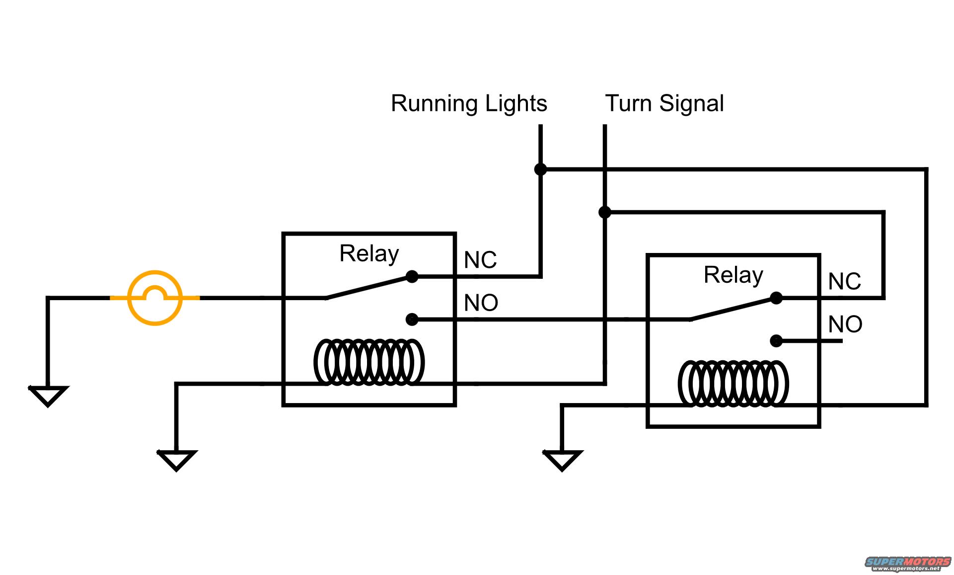
Running Light + Turn Signal Combined via Two Relays - Wiring Diagram Schematic
Reference · 2011-2016 F-550All 21 wiring diagrams
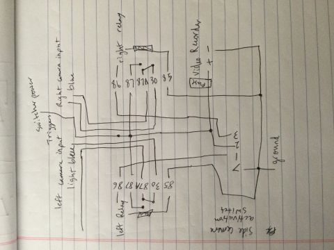
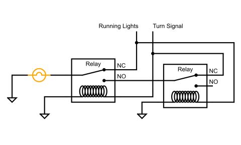
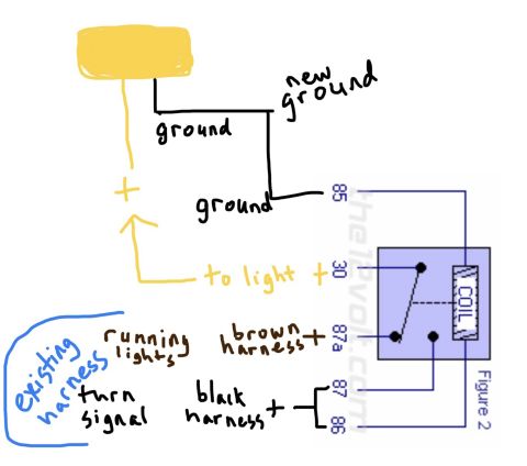




Wiring diagram showing two relays wired to running-light and turn-signal feeds with normally-open and normally-closed contacts.
Part of 2011-2016 Ford F-550 Wiring Diagrams
This document is a hand-drawn style electrical schematic (not a fuse box chart) showing how to combine a vehicle's running lights and turn signal circuits to drive a single lamp using two relays. Two labeled inputs, "Running Lights" and "Turn Signal," feed a pair of SPDT relays, each shown with a coil, a normally closed (NC) contact, and a normally open (NO) contact. A single lamp (drawn in orange) is wired between ground and the common switch contact of the first relay. The Turn Signal circuit energizes the left relay's coil, while the Running Lights circuit feeds the left relay's NC contact and also relates to the right relay's coil circuit; the left relay's NO path routes through the right relay's contacts. Three chassis ground symbols are shown for the lamp return and each relay coil. A reader can learn the interconnection logic for making one bulb serve as both a running light and a turn signal, with the turn signal taking priority when active, a common setup for custom lighting, trailer wiring, or aftermarket LED conversions. The diagram contains no year, model, part numbers, wire colors, or fuse information.
Is this accurate? Sign in to help verify it.
Frequently asked questions
- What does this wiring diagram show?
- It shows two relays wired so that a single lamp is driven by both the Running Lights and Turn Signal circuits, using each relay's NC and NO contacts and coils, with grounds for the lamp and both relay coils.
- How is the lamp connected in this diagram?
- The lamp (shown in orange) is wired between a chassis ground on the left and the common switch contact of the first (left) relay.
- What energizes the left relay's coil?
- The Turn Signal line is routed down to the left relay's coil; the coil's other side goes to ground.
- Where does the Running Lights feed go?
- The Running Lights line connects to the left relay's NC contact and also runs across the top of the diagram to the right relay's circuit.
- Does this diagram list fuses, wire colors, or part numbers?
- No. The only text in the diagram is 'Running Lights', 'Turn Signal', 'Relay' (twice), and the contact labels 'NC' and 'NO'. No fuse ratings, wire colors, or part numbers appear.
No comments yet.