Home/
Registry/
Ford/
F-550/
2011-2016/
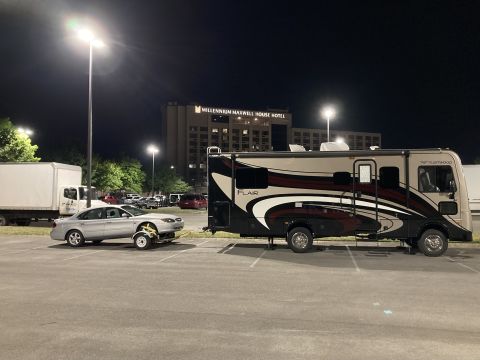
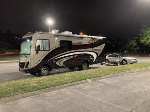
“F53 16K Fleetwood Flair”/
Photo
supermotors.net/registry/media/1165924
Dual Camera Switcher Relay Wiring Diagram - Left/Right Trigger to Video Recorder

Wiring diagram of a camera-switcher circuit using two relays and a left-off-right switch feeding a video recorder.
Part of 2011-2016 Ford F-550 Wiring Diagrams
This document is a hand-drawn/CAD-style electrical wiring schematic showing how a camera switcher unit is wired to a video recorder through two relays and a manual selector switch. The camera switcher has three output lines labeled Camera Switcher Power, Right Camera Trigger, and Left Camera Trigger, plus a Ground Rail connection. Two relays are drawn, each with normally closed (NC) and normally open (NO) contacts and a coil. The relay contacts route the Right and Left Camera Trigger lines, while the coils are energized via a three-position 'Left -Off-Right' toggle switch. The switch output passes through a 5 A fuse before reaching the Video Recorder connection. The diagram illustrates how flipping the Left-Off-Right switch selects which camera trigger circuit (left or right) is activated, allowing the video recorder to receive or trigger the appropriate camera feed. No part numbers, wire colors, connector pin identifiers, or vehicle-specific year/model information appear on the drawing. A reader can learn the logical wiring topology needed to build or troubleshoot a dual-camera switching setup with relay isolation and fused power to the recorder, such as an auxiliary backup/side camera system installed in a truck.
Is this accurate? Sign in to help verify it.
Frequently asked questions
- What fuse rating is used in this camera switcher circuit?
- A 5 A fuse is shown in line before the Video Recorder connection.
- What kind of switch controls the relays in this diagram?
- A three-position 'Left -Off-Right' switch selects which relay coil is energized, choosing the left or right camera or turning the circuit off.
- What connections does the camera switcher have in this schematic?
- The camera switcher has three lines, Camera Switcher Power, Right Camera Trigger, and Left Camera Trigger, plus a connection to the Ground Rail.
- How are the relays configured?
- Each of the two relays has a coil and a contact set with NC (normally closed) and NO (normally open) positions that switch the right and left camera trigger lines.
- Does this diagram specify wire colors or part numbers?
- No. The diagram contains only functional labels; no wire colors, connector pins, or part numbers are shown.
Comments
More from this build
No comments yet.