Home/
Registry/
Ford/
F-550/
2011-2016/
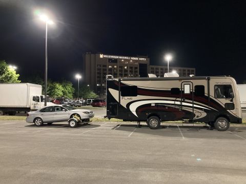
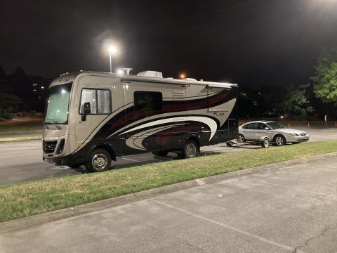
“F53 16K Fleetwood Flair”/
Photo
supermotors.net/registry/media/1169307
RV Rooftop A/C Wiring Diagram Label 1976E136 - Fan Motor, Compressor & Start Relay

Bilingual HVAC condenser fan-motor wiring label showing optional start wiring: purple and black wires spliced when no start relay used, with run cap, start cap, PTCR and potential relay configurations.
Part of 2011-2016 Ford F-550 Wiring Diagrams
This document is a photographed yellow wiring diagram label affixed to a sheet-metal panel, apparently from a rooftop air conditioner unit. It shows the internal wiring of the unit's fan motor (HIGH/LOW/COM terminals wired with BLK, RED, and WHT wires), a fan capacitor connected via BRN/WHT and BRN wires, and a numbered 9-pin plug that connects to the ceiling assembly (pin 9 WHT, pin 7 GRN/ground, pin 6 RED, pin 5 BLK, pin 3 PUR, pin 1 YEL). Two alternative compressor start-circuit schematics are shown: one using a positive temperature coefficient resistor (P.T.C.R.) with an optional start capacitor, and one using a potential motor starting relay (terminals 1, 2, 5) with a start capacitor. Both feed the compressor and overload, whose terminals are labeled R, C, and S. Notes state that dashed lines indicate optional start components and wiring, and that purple and black wires are spliced together when no start relay is used. A bilingual (English/French) shock-hazard caution instructs disconnecting the power supply before servicing any electrical component. The label bears the number 1976E136 (2-14) P.P. Readers can learn wire colors, plug pinout, and start-component configurations for troubleshooting this A/C unit.
Is this accurate? Sign in to help verify it.
Frequently asked questions
- What do the dashed lines on this wiring diagram mean?
- Dashed lines indicate optional start components and wiring, such as the start capacitor, P.T.C.R., and start relay.
- What happens to the purple and black wires if no start relay is used?
- The label states that the purple and black wires are spliced together when no start relay is used.
- What is the pinout of the plug that connects to the ceiling assembly?
- Pin 9 = WHT, pin 7 = GRN (ground), pin 6 = RED, pin 5 = BLK, pin 3 = PUR, pin 1 = YEL; pins 8, 4, and 2 show no wires. Additional wiring is per the diagram supplied with the ceiling assembly.
- What wire colors connect the fan motor speeds?
- BLK connects to HIGH, RED to LOW, and WHT to COM on the fan motor; BRN/WHT and BRN run to the fan capacitor.
- What safety warning is on the label?
- CAUTION! SHOCK HAZARD! Disconnect power supply before servicing any electrical component (also given in French).
Comments
More from this build


No comments yet.