Home/
Registry/
Ford/
F-550/
2011-2016/
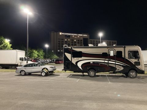
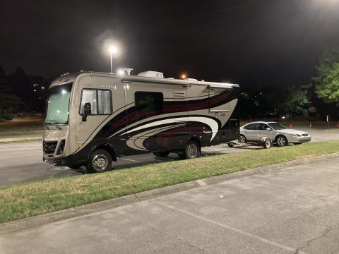
“F53 16K Fleetwood Flair”/
Photo
supermotors.net/registry/media/1165963
Blue Sea 7931 Contura II Switch Wiring Diagram - SPDT ON-OFF-ON Pin Out

Wiring pin-out diagram on a Blue Sea Systems Contura II SPDT switch card showing power, ground, LED and load 1/2 terminal connections.
Part of 2011-2016 Ford F-550 Wiring Diagrams
This document is the yellow product/instruction label for a Blue Sea Systems Contura II rocker switch, part number 7931, with a Black/Red actuator (Blk/Red). The label identifies the switch as an SPDT (single pole, double throw) ON-OFF-ON type that "turns one of two circuits on" and features two ON-indicating LEDs. The main content is a PIN Out Diagram that shows how to wire the switch: pin 7 is the LED GROUND, pin 1 is LOAD 1, pin 2 is POWER (the common feed to the switch pole), and pin 3 is LOAD 2. The diagram depicts the internal switching arrangement, with the pole at pin 2 selecting between the two load pins, and LED indicator symbols associated with each load circuit so the corresponding LED lights when that circuit is energized. A reader can learn the correct terminal assignments for installing this switch in a 12V accessory circuit, where to connect power, the two loads, and the LED ground. The label contains no vehicle-specific application data; it was uploaded to a 2015 Ford F-550 gallery, presumably documenting an accessory switch installation on that truck.
Is this accurate? Sign in to help verify it.
Frequently asked questions
- What is the pin out for the Blue Sea 7931 Contura II switch?
- Per the label's PIN Out Diagram: pin 7 is LED GROUND, pin 1 is LOAD 1, pin 2 is POWER, and pin 3 is LOAD 2.
- What type of switch is the Blue Sea 7931?
- It is an SPDT ON-OFF-ON Contura II switch that turns one of two circuits on, with two ON-indicating LEDs. The actuator color is Blk/Red.
- Which terminal gets the power feed on this switch?
- Pin 2 is labeled POWER; it is the common terminal that switches to LOAD 1 (pin 1) or LOAD 2 (pin 3).
- How are the indicator LEDs wired on this switch?
- The two ON-indicating LEDs share pin 7 as the LED GROUND, and each LED corresponds to one of the two load circuits shown in the diagram.
Comments
More from this build


No comments yet.