Home/
Registry/
Ford/
F-550/
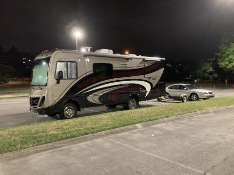
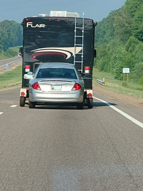
“F53 16K Fleetwood Flair”/
Photo
supermotors.net/registry/media/1170036
ARG 12V Electrical Floor Plan 732-26E Motorhome Wiring Diagram 19H90140 (2014)
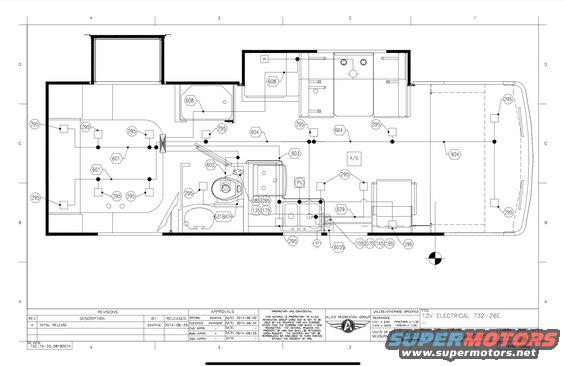
RV 12V electrical layout schematic showing component locations on a motorhome floorplan with engineering title block and revisions.
This is Sheet 1 of 2 of an Allied Recreation Group (ARG) engineering drawing, DWG No. 19H90140 revision A, titled "12V ELECTRICAL 732-26E." It is a top-down floor plan of a motorhome coach body (floor plan 732-26E) showing the physical locations and wiring runs of 12-volt DC electrical components. Numbered balloon callouts identify component/circuit locations throughout the coach: 601 and 602 circuits in the front and bath areas, 603/603S mid-coach, 604 ceiling runs toward the rear, 608 at the shower and rear bedroom, 629 near the dinette/seating area, 631BATH in the bathroom, and many "295" callouts (likely ceiling lights) distributed front to rear. Circle callouts 085/095/135/175 and 105/075/145/195 are grouped in the kitchen area, with additional labels for A/C (roof air conditioner), PV (power vents), R, P, and S (switch) locations. The title block shows the drawing was drawn 2014-06-20 by 044hilla, checked 2014-06-24 by 044kipfef, and released 2014-06-25 as the initial release (Rev A). Scale 1:1, size B, units inches, third-angle projection, with ARG's proprietary/confidential notice. DC info reads 732_15-33_08182014. A reader can learn the placement of 12V fixtures, switches, and wiring routing points in this specific coach floor plan.
Is this accurate? Sign in to help verify it.
Frequently asked questions
- What does drawing 19H90140 show?
- It is Sheet 1 of 2 of Allied Recreation Group drawing 19H90140, titled '12V ELECTRICAL 732-26E,' a floor-plan layout showing 12V electrical component locations and wiring runs in the coach.
- What revision is this drawing and when was it released?
- Revision A, 'Initial Release,' released 2014-06-25. It was drawn 2014-06-20 by 044hilla and checked 2014-06-24 by 044kipfef.
- What callout numbers appear on the floor plan?
- Hexagon callouts 601, 602, 603, 603S, 604, 608, 629, and 631BATH; numerous circle callouts labeled 295; grouped circles 085, 095, 135, 175 and 105, 075, 145, 195; plus labels R, A/C, PV, P, and S switch symbols.
- Who owns this drawing and can it be reproduced?
- It is proprietary to Allied Recreation Group (ARG). Per the notice, it may not be reproduced or disclosed to third parties without ARG's consent.
- What are the drawing scale, size, and units?
- Scale 1:1, size B sheet, units of measure in inches, drawn in third-angle projection with tolerances of ±0.03 (X.XX), ±0.015 (X.XXX), ±1/32 fractions, and ±1/32 angles.
Comments
More from this build

No comments yet.