Home/
Registry/
Ford/
F-550/
2011-2016/
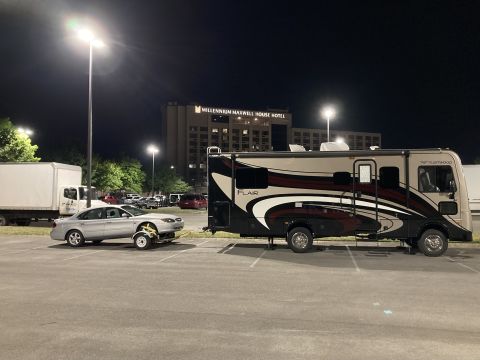
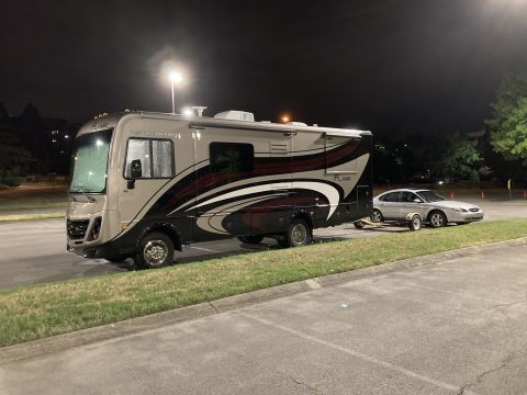
“F53 16K Fleetwood Flair”/
Photo
supermotors.net/registry/media/1169663
Carling-Style Rocker Switch Wiring Diagram - Generator & House Battery Pinout

Switch terminal wiring diagram sheet showing rocker-switch positions and positive, negative and output connections
Part of 2011-2016 Ford F-550 Wiring Diagrams
This document is a photographed instruction/wiring sheet for Carling-style rocker switches, shown alongside two physical switch bodies and two snap-on actuator covers labeled "GENERATOR" (lightning bolt icon) and "HOUSE BATTERY" (battery icon). The sheet provides terminal pinout diagrams for a DPDT-style ON/(ON) rocker switch: terminals 1 (Positive 1 OUT, switch down), 2 (Positive 1 IN), 3 (Positive 1 OUT, switch up), 4 (Positive 2 OUT, switch down), 5 (Positive 2 IN), and 6 (Positive 2 OUT, switch up). A second diagram covers an illuminated latching/momentary variant: terminal 8 = indicator lamp (+), 7 = negative, 2 = positive in, 3 = positive out (latching), 5 = positive in (via a pre-installed T2-T5 jumper), and 6 = positive out (momentary). Numbered notes explain that a removable jumper joins terminals 2 and 5, that the latching center ON position uses terminals 2/3, that the momentary top ON position uses terminals 5/6, and that the latching center ON position is maintained while the momentary position is pressed. Common uses listed include START/RUN/OFF for engine switches and WASH/WIPER/OFF for wiper/washer fluid switches. Useful for anyone wiring generator or house-battery rocker switches in an RV or truck upfit.
Is this accurate? Sign in to help verify it.
Frequently asked questions
- What do the terminals on this rocker switch do?
- Terminals 1, 2, 3 are Positive 1 OUT (switch down), IN, and OUT (switch up); terminals 4, 5, 6 are the same for Positive 2. On the illuminated version, 8 is the indicator lamp (+), 7 is negative, 2 is positive in, 3 is positive out (latching), 5 is positive in, and 6 is positive out (momentary).
- What is the jumper between terminals 2 and 5 for?
- The switch comes with a pre-installed but removable T2-T5 jumper connecting terminals 2 and 5. It is normally left in place unless separate feeds are needed for the momentary and latching positions.
- Which terminals are used for the latching and momentary positions?
- The latching center ON position is between terminals 2 and 3, while the momentary top ON position is between terminals 5 and 6. The latching center ON position is maintained while the momentary position is pressed.
- What are common uses for this switch listed in the instructions?
- START/RUN/OFF for engine switches and WASH/WIPER/OFF for wiper/washer fluid switches.
- What labels are on the included switch covers?
- One actuator cover is labeled GENERATOR with a lightning bolt icon, and the other is labeled HOUSE BATTERY with a battery icon.
Comments
More from this build


No comments yet.