Home/
Registry/
Ford/
Bronco/
1966-1977/
1976 Ford Bronco/
Photo
supermotors.net/registry/media/1166467
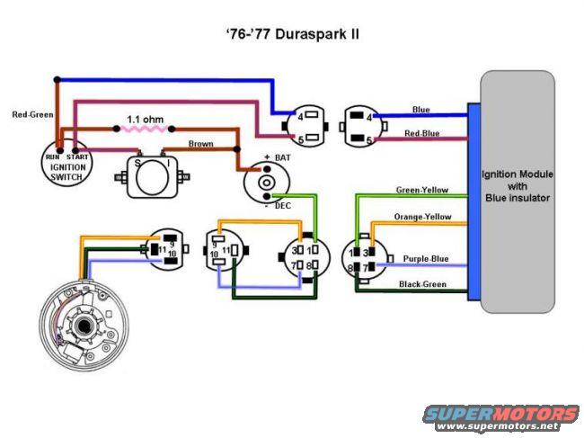
1976-1977 Ford Duraspark II Ignition Wiring Diagram - Blue Grommet Module
Reference · 1966-1977 BroncoAll 10 wiring diagrams
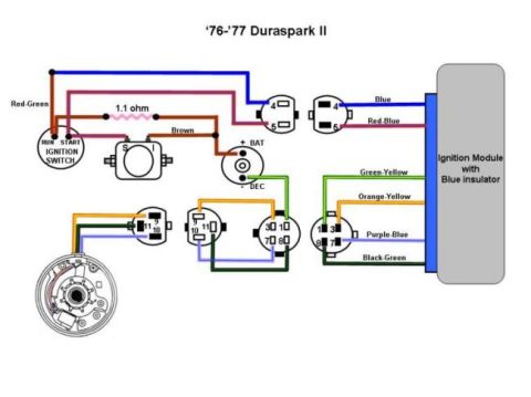
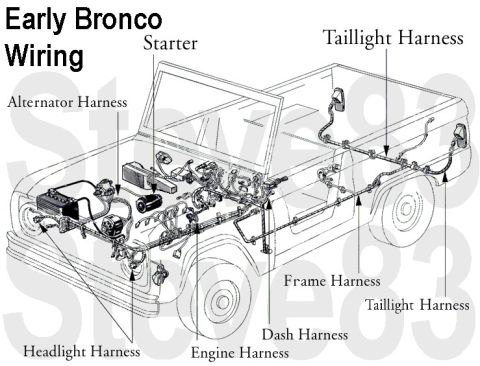
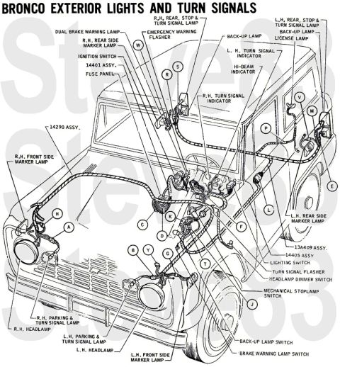
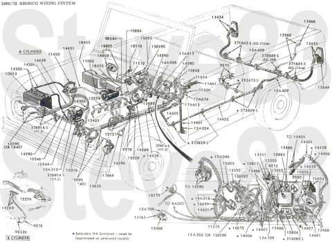
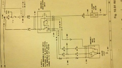
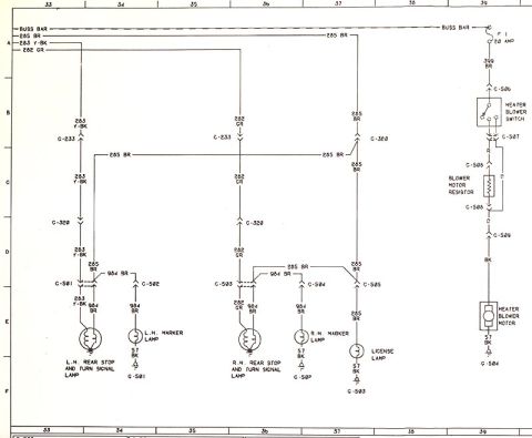
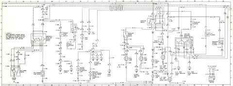
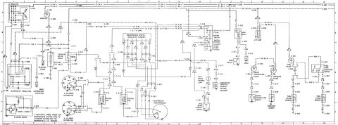
Wiring diagram of a 1976-77 Ford Duraspark II ignition showing ignition switch, ballast, connectors and color-coded wires to the ignition module.
Part of 1966-1977 Ford Bronco Wiring Diagrams
This document is a color-coded wiring diagram for the 1976-1977 Ford Duraspark II ignition system. It shows the ignition switch with RUN and START terminals feeding the circuit: a Red-Green wire supplies power in START, and a Brown wire through a 1.1 ohm ballast resistor supplies power in RUN. Power routes to the ignition coil, whose terminals are marked + BAT and - DEC, and to the starter solenoid (terminals S and I). The diagram details the connector pinouts between the harness, distributor pickup, and the ignition module, which is identified as the version with a blue insulator (blue grommet). Wire colors to the module are labeled: Blue, Red-Blue, Green-Yellow, Orange-Yellow, Purple-Blue, and Black-Green. Connector pin numbers shown include 4 and 5 on the two-pin connector, 9/10/11 on the distributor pickup connector, and 1/3/7/8 on the four-pin module connector. A reader can use this diagram to wire or troubleshoot a Duraspark II ignition conversion or repair on a '76-'77 Ford, verifying correct wire colors, pin assignments, resistor value, and coil/solenoid connections.
Is this accurate? Sign in to help verify it.
Frequently asked questions
- What ignition module does this diagram apply to?
- The '76-'77 Duraspark II ignition module with the blue insulator (blue grommet).
- What is the ballast resistor value in the Duraspark II circuit?
- 1.1 ohm, in the Brown wire circuit between the ignition switch RUN feed and the coil.
- What wire colors connect to the blue-grommet Duraspark II module?
- Blue, Red-Blue, Green-Yellow, Orange-Yellow, Purple-Blue, and Black-Green.
- How is the ignition coil connected?
- The coil's + BAT terminal receives power (via the resistor circuit and starter solenoid I terminal path), and the - DEC terminal connects toward the module/distributor side.
- What pins are used on the module connectors?
- A two-pin connector uses pins 4 and 5; the distributor pickup connector uses pins 9, 10, and 11; and a four-pin connector uses pins 1, 3, 7, and 8.

No comments yet.