Home/
Registry/
Ford/
Taurus/
1996-1999/
1997 Ford Taurus/
Photo
supermotors.net/registry/media/167089
1997 Ford Taurus RCC Module Connector C2044 Pinout - Climate Control Wiring

Reference · 1996-1999 TaurusAll 4 fuse & relay charts
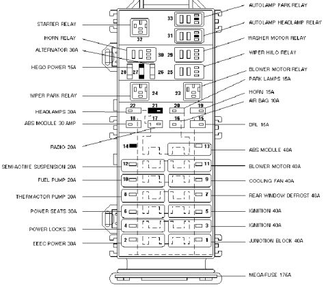
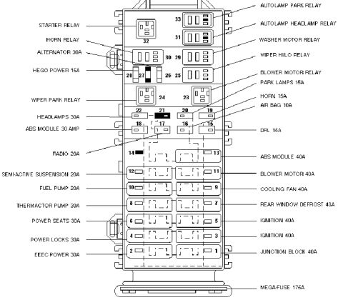
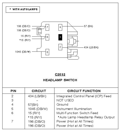
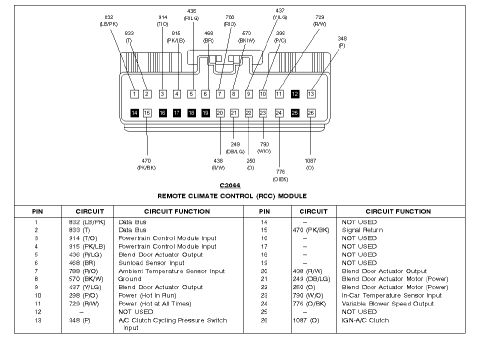
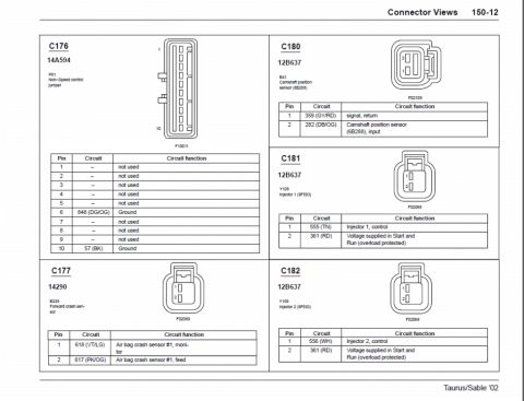
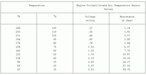
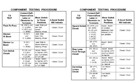
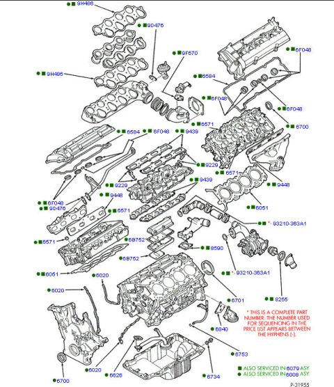

Connector pinout chart for the Remote Climate Control (RCC) module C2044, mapping each pin number to its circuit and function.
Part of 1996-1999 Ford Taurus Fuse & Relay Charts
This document is a connector pinout diagram and table for connector C2044, the Remote Climate Control (RCC) Module, uploaded as applying to a 1997 Ford Taurus. It shows a 26-pin connector face view: pins 1-13 on the top row and pins 14-26 on the bottom row, with several pins (12, 14, 16-19, 25) marked as unused. Callout labels around the connector identify each circuit number and wire color code (e.g., 832 LB/PK, 833 T, 914 T/O, 915 PK/LB, 436 R/LG, 468 BR, 788 R/O, 570 BK/W, 437 Y/LG, 298 P/O, 729 R/W, 348 P on top; 470 PK/BK, 438 R/W, 249 DB/LG, 250 O, 790 W/O, 776 O/BK, 1087 O on bottom). An accompanying table lists every pin's circuit number, wire color, and function, including data bus lines, powertrain control module inputs, blend door actuator outputs and motor power, sunload/ambient/in-car temperature sensor inputs, ground, signal return, hot-in-run and hot-at-all-times power feeds, A/C clutch cycling pressure switch input, variable blower speed output, and IGN-A/C clutch. This is useful for diagnosing electronic automatic climate control (EATC) wiring problems.
Is this accurate? Sign in to help verify it.
Frequently asked questions
- What connector is shown in this diagram?
- Connector C2044, which plugs into the Remote Climate Control (RCC) Module. It has 26 pins arranged in two rows (1-13 and 14-26).
- Which pins on the RCC module connector are not used?
- Pins 12, 14, 16, 17, 18, 19, and 25 are marked NOT USED.
- Which pins provide power and ground to the RCC module?
- Pin 10 is circuit 298 (P/O), Power (Hot In Run); pin 11 is circuit 729 (R/W), Power (Hot at All Times); pin 8 is circuit 570 (BK/W), Ground; pin 15 is circuit 470 (PK/BK), Signal Return.
- Which pins connect to the temperature sensors?
- Pin 6 (468 BR) is the Sunload Sensor Input, pin 7 (788 R/O) is the Ambient Temperature Sensor Input, and pin 23 (790 W/O) is the In-Car Temperature Sensor Input.
- What pin controls the blower speed?
- Pin 24, circuit 776 (O/BK), is the Variable Blower Speed Output.




No comments yet.