Home/
Registry/
Ford/
Taurus/
1996-1999/
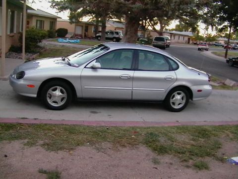
1997 Ford Taurus/
Photo
supermotors.net/registry/media/167090
1997 Ford Taurus EATC Climate Control Sensor Wiring Diagram - RCC, PCM, PATS

Reference · 1996-1999 TaurusAll 33 wiring diagrams
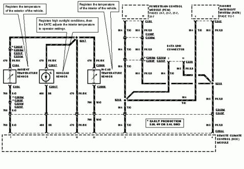
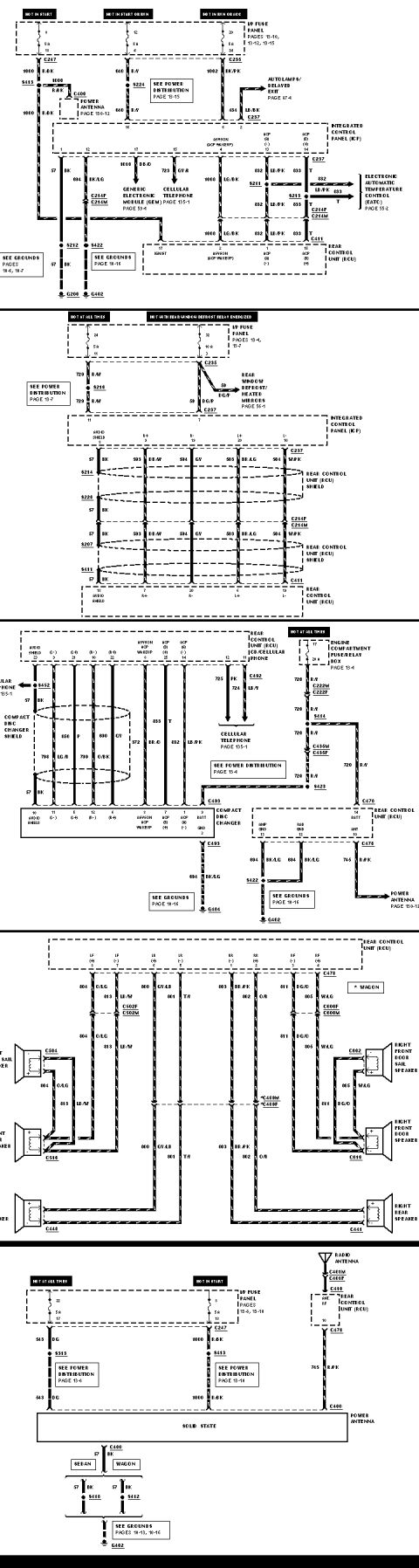
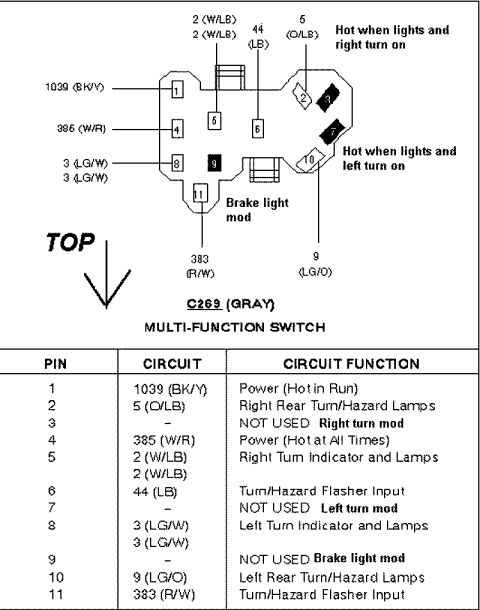

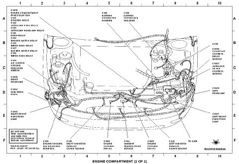
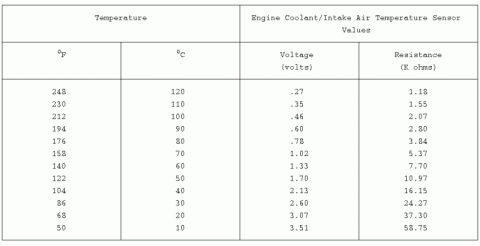

Wiring diagram showing ambient, in-car and sunload temperature sensors connected to the PCM and data link connector with circuit codes.
Part of 1996-1999 Ford Taurus Wiring Diagrams
This document is a factory-style wiring diagram covering the climate control sensor circuits for a Ford Taurus with Electronic Automatic Temperature Control (EATC). It shows three sensors, the Ambient Temperature Sensor (registers exterior temperature), the In-Car Temperature Sensor (registers interior temperature), and the Sunload Sensor (registers high sunlight so the EATC can adjust interior temperature), and their wiring to the Remote Climate Control (RCC) Module. Circuit numbers and wire colors are given: 470 PK/BK (sensor supply/reference), 788 R/O (ambient sensor return to RCC pin 7), 468 BR (sunload sensor return to RCC pin 6), and 790 W/O (in-car sensor return to RCC pin 23). The diagram also shows data link wiring: circuits 914 T/O and 915 PK/LB running from the Powertrain Control Module (PCM, pins 16/15, pages 24-7, 23-7, 25-7, 26-7) and the Passive Anti-Theft System (PATS, page 112-1) through the Data Link Connector (pins 2 and 10) to RCC pins 3 and 4. Connectors identified include C164, C2017, C2000, C191, C130F/C130M, C221F/C221M, C229, C242, C243M/C243F, C2044, and early-production connectors C263F/C263M (noted as applying to early production 3.0L 4V or 3.4L SHO), plus splices S217, S218 and S219.
Is this accurate? Sign in to help verify it.
Frequently asked questions
- What does the sunload sensor do on the Ford Taurus EATC system?
- It registers high sunlight conditions, and the EATC then adjusts the interior temperature to operator settings.
- What wire color and circuit connect the in-car temperature sensor to the RCC module?
- The in-car temperature sensor uses circuit 470 PK/BK for supply and circuit 790 W/O returning to RCC module pin 23; 470 PK/BK also goes to RCC pin 15.
- Which RCC module pins do the climate control sensors use?
- Ambient temperature sensor: pin 7 (788 R/O); sunload sensor: pin 6 (468 BR); in-car temperature sensor: pins 23 (790 W/O) and 15 (470 PK/BK). Data link circuits use pins 3 (914 T/O) and 4 (915 PK/LB).
- What do the asterisked connectors C263F and C263M apply to?
- Per the footnote, the asterisked items apply to early production 3.0L 4V or 3.4L SHO vehicles.
- What data link circuits connect the PCM and PATS to the RCC module?
- Circuits 914 T/O and 915 PK/LB run from PCM pins 16/15 and PATS pins 6/5 through the Data Link Connector (pins 2 and 10) to RCC pins 3 and 4, via connectors including C191, C130F/M, C229, C242, C243M/F and C2044.




No comments yet.