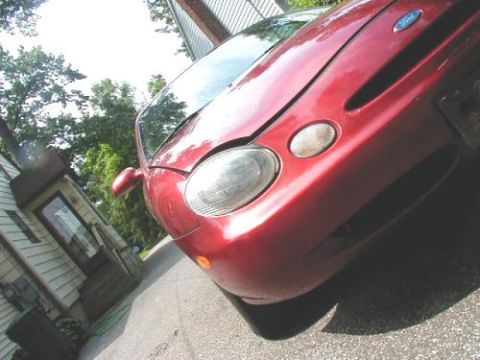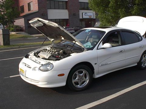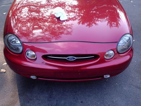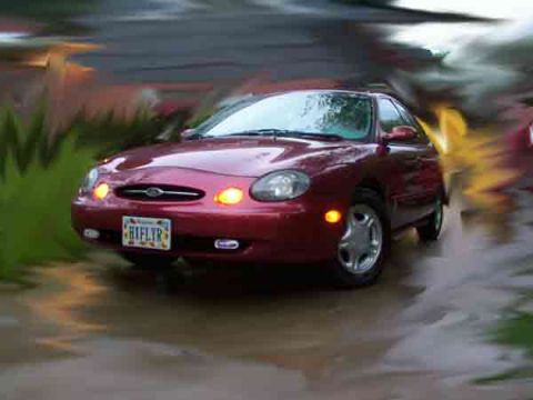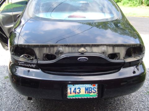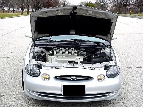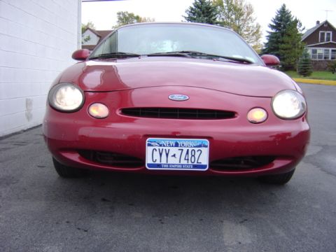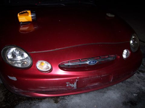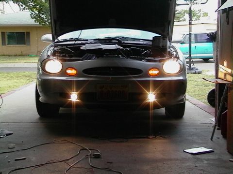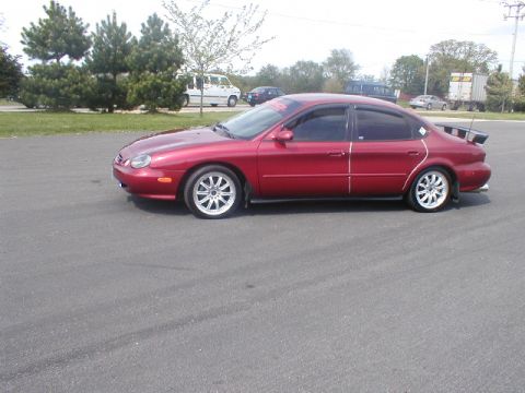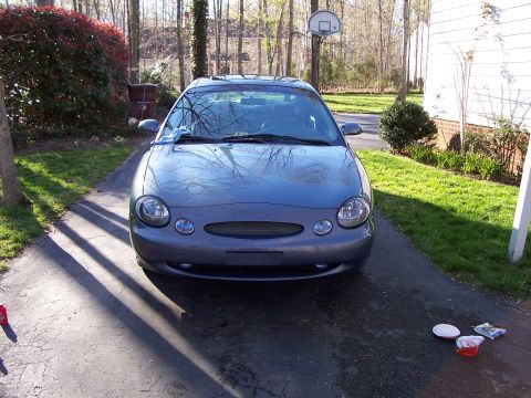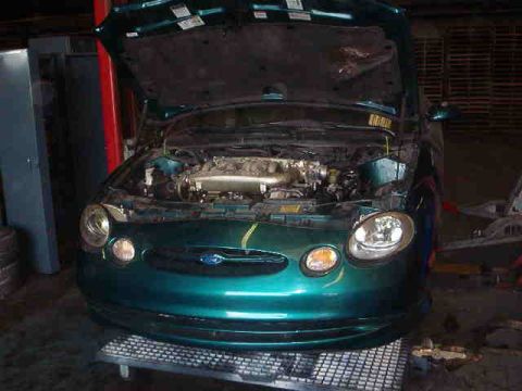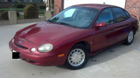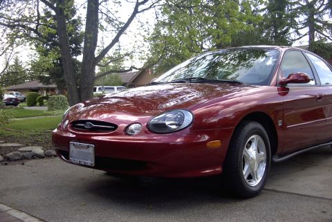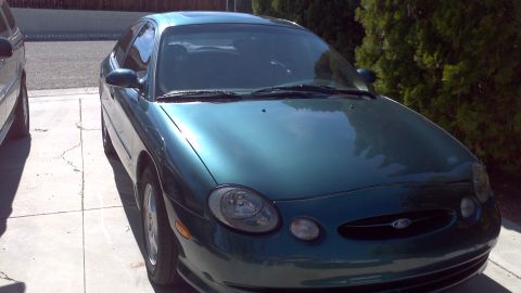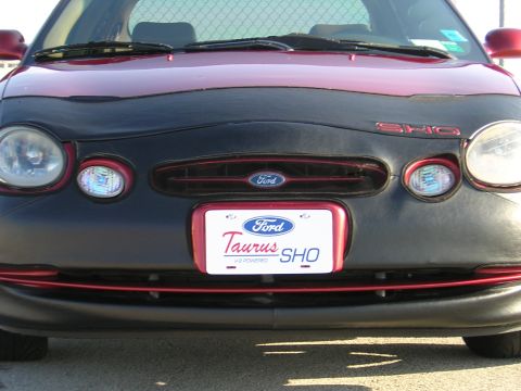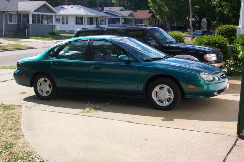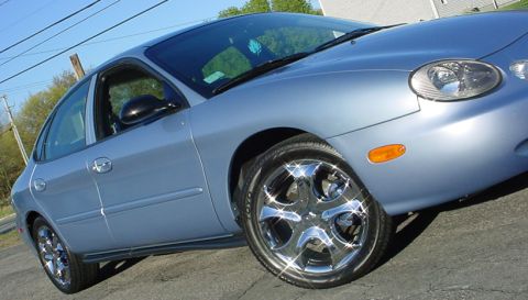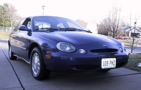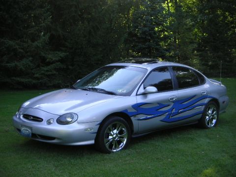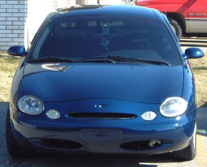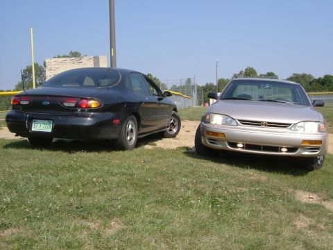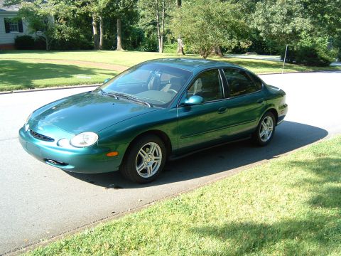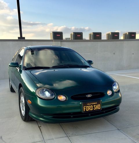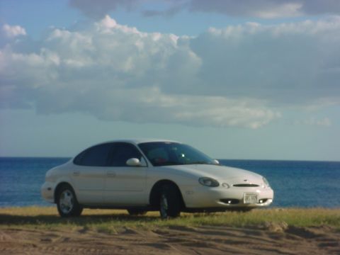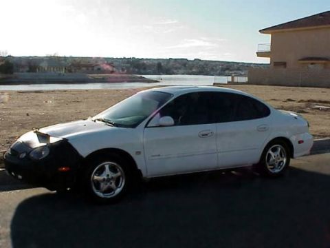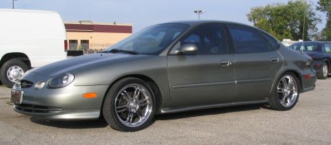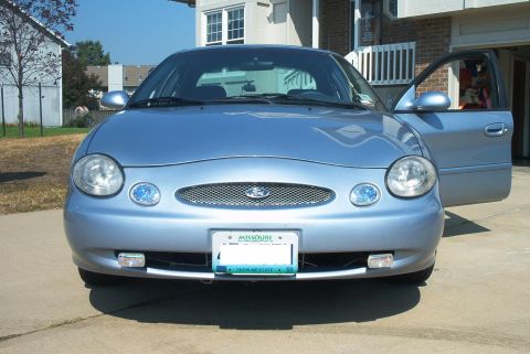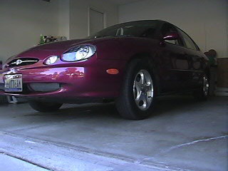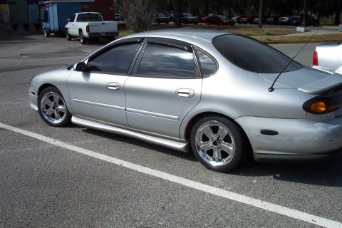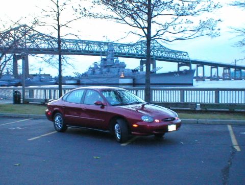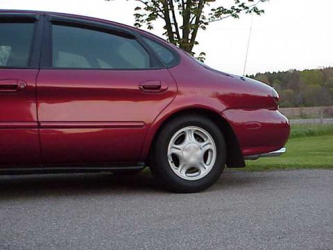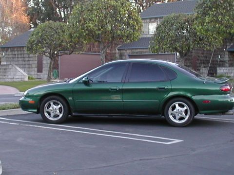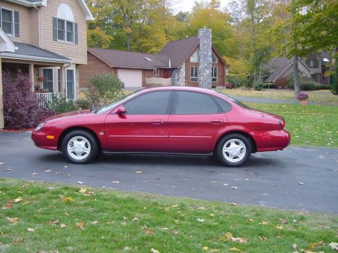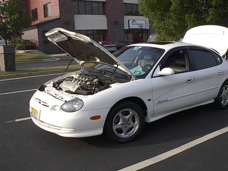
The 1996 model year brought the third-generation Ford Taurus, a full redesign built around an oval styling theme that extended from the grille and rear window to interior details. The engine lineup changed: the pushrod Vulcan 3.0 V6, rated at 145 horsepower, continued as the base engine, while a new dual-overhead-cam Duratec 3.0 V6, rated at 200 horsepower, was offered on the upper LX trim, both with a four-speed automatic. The performance Taurus SHO switched from the Yamaha V6 of earlier years to a 3.4 Yamaha V8, a 60-degree dual-overhead-cam 32-valve engine rated at 235 horsepower and 230 lb-ft of torque, paired only with the four-speed AX4N automatic. This was the only V8-powered Taurus SHO, and it ran for four model years, 1996 through 1999. The oval theme was not well received, and the Taurus lost its position as the best-selling car in the United States to the Toyota Camry for the 1997 model year after holding it from 1992 through 1996. The 3.4 SHO V8 later became known for a camshaft-sprocket failure traced to how Yamaha attached the sprockets to the camshafts. The Mercury Sable continued as the badge-engineered sibling.
Other Ford Taurus generations
The 1996-1999 Ford Taurus at a glance
- Generation: third-generation Ford Taurus, the oval-themed full redesign
- Years: 1996 through 1999, replaced by the fourth-generation Taurus for 2000
- Engines: pushrod Vulcan 3.0 V6 (145 hp); Duratec 3.0 DOHC V6 (200 hp); SHO Yamaha 3.4 V8 (235 hp)
- Transmissions: four-speed automatic on standard models; four-speed AX4N automatic on the SHO V8
- Body styles: four-door sedan and four-door wagon
- Sales: best-selling car in the United States for 1996, then lost the title to the Toyota Camry for 1997
- Performance variant: Taurus SHO with the 3.4 Yamaha V8, the only V8 Taurus, built 1996-1999
- Known issue: the 3.4 SHO V8 camshaft-sprocket failure
Ford Taurus 1996-1999 year by year
| Year | Ford Taurus changes | Engines offered |
|---|---|---|
| 1996 | Third-generation Ford Taurus arrives with the oval styling theme; the Duratec 3.0 DOHC V6 joins the lineup and the SHO switches to a 3.4 Yamaha V8 | Vulcan 3.0 V6; Duratec 3.0 V6; SHO 3.4 V8 |
| 1997 | The Ford Taurus loses its best-selling-car title in the United States to the Toyota Camry; the oval-theme lineup continues | Vulcan 3.0 V6; Duratec 3.0 V6; SHO 3.4 V8 |
| 1998 | The 1998 Ford Taurus continues the third-generation sedan, wagon, and SHO lineup | Vulcan 3.0 V6; Duratec 3.0 V6; SHO 3.4 V8 |
| 1999 | Final model year of the third-generation Ford Taurus and the last year of the V8 SHO | Vulcan 3.0 V6; Duratec 3.0 V6; SHO 3.4 V8 |
The oval redesign
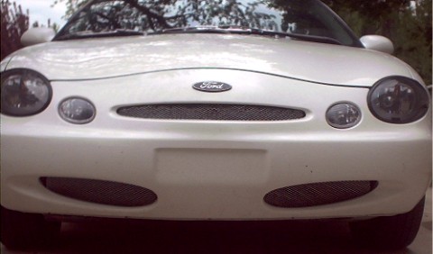
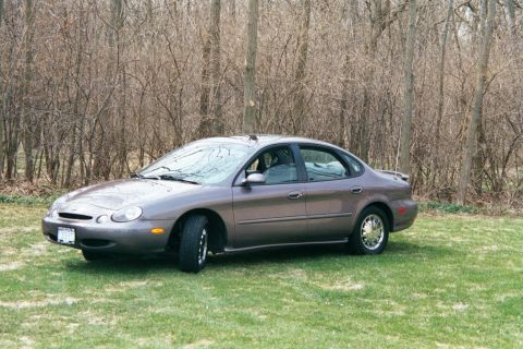
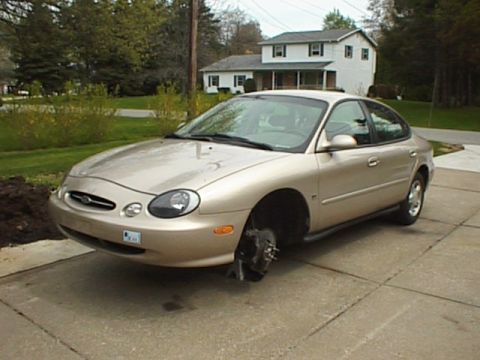
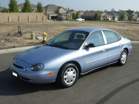
The 1996 Ford Taurus was a full redesign that applied an oval styling theme across the car, including an oval grille, oval rear window, and oval interior elements. The redesign was more divisive than the first two generations, and the styling is commonly cited as a reason the Taurus lost momentum against rivals such as the Toyota Camry. The third-generation Taurus was offered as a four-door sedan and a four-door wagon, with the Mercury Sable as the badge-engineered counterpart. The Taurus remained the best-selling car in the United States for the 1996 model year, then ceded the title to the Camry for 1997.
Engines and transmissions of the 1996-1999 Ford Taurus
The base engine of the 1996-1999 Ford Taurus was the pushrod Vulcan 3.0 V6, a two-valve-per-cylinder engine rated at 145 horsepower at 5250 rpm and 170 lb-ft of torque. The upper engine was the new dual-overhead-cam Duratec 3.0 V6, a four-valve-per-cylinder engine rated at 200 horsepower at 5750 rpm and 200 lb-ft of torque, offered on the LX. Both standard engines used a four-speed automatic. The Duratec 3.0 marked the Taurus's move to a modern dual-overhead-cam V6 alongside the older pushrod engine.
Trim levels and body styles
The 1996-1999 Ford Taurus was offered in trims that included the G and GL with the Vulcan 3.0 V6, the LX with the Duratec 3.0 V6, and the performance SHO with the 3.4 V8. Both the four-door sedan and the four-door wagon were available, while the SHO was a sedan. The Mercury Sable provided a parallel lineup under a separate badge.
The V8 Taurus SHO (1996-1999)
The third-generation Taurus SHO replaced the earlier Yamaha V6 with a 3.4 Yamaha V8, a 60-degree dual-overhead-cam 32-valve engine based on the Duratec family rather than the older SHO V6. It used an aluminum block and a structural aluminum oil pan, making it lighter than the iron-block V6, and was rated at 235 horsepower and 230 lb-ft of torque. The only transmission was the four-speed AX4N automatic, so unlike the earlier V6 SHO the V8 SHO was never offered with a manual. The engines were assembled by Yamaha in Japan. This was the only V8-powered Taurus SHO, built across the 1996 through 1999 model years; about 19,730 V8 SHOs were produced. The 3.4 V8 became known for a camshaft-sprocket failure, in which a sprocket could break loose from its camshaft because of the swaging method Yamaha used to attach it; many owners had the sprockets welded or pinned as a preventive measure.
Frequently asked questions
What generation is the 1996-1999 Ford Taurus?
The 1996-1999 Ford Taurus is the third generation, the oval-themed full redesign. It introduced the Duratec 3.0 dual-overhead-cam V6 and switched the SHO to a 3.4 Yamaha V8, and it is the generation in which the Taurus lost the U.S. sales crown to the Toyota Camry.
What engines did the 1996-1999 Ford Taurus use?
The 1996-1999 Ford Taurus used the pushrod Vulcan 3.0 V6 rated at 145 horsepower as the base engine and the new dual-overhead-cam Duratec 3.0 V6 rated at 200 horsepower on the LX. The performance SHO used a 3.4 Yamaha V8 rated at 235 horsepower.
What is the difference between the Vulcan and Duratec V6?
In the 1996-1999 Ford Taurus, the Vulcan 3.0 is a pushrod (overhead-valve) two-valve V6 rated at 145 horsepower, while the Duratec 3.0 is a dual-overhead-cam four-valve V6 rated at 200 horsepower. The Duratec was the upper engine on the LX.
Did the V8 Taurus SHO have a manual transmission?
No. The 1996-1999 Ford Taurus SHO used the 3.4 Yamaha V8 paired only with the four-speed AX4N automatic. Within the SHO line, a manual transmission was offered only on the earlier Yamaha V6 SHO of 1989 through 1995.
What is the 3.4 SHO V8 camshaft-sprocket problem?
The 3.4 Yamaha V8 in the 1996-1999 Taurus SHO could suffer a camshaft-sprocket failure, in which a sprocket broke loose from its camshaft because of the swaging method used to attach it. When that happened the camshaft stopped turning the valves, which could damage the engine, so many owners welded or pinned the sprockets as a preventive fix.
Sources
- Wikipedia, Ford Taurus (third generation)
- Wikipedia, Ford SHO V8 engine
- Ford-Taurus.org Taurus/Sable Encyclopedia, third-generation history
- V8SHO.com camshaft-sprocket failure documentation
- Manufacturer specification figures and contemporary sales reporting
Asked all the time
What generation is the 1996-1999 Ford Taurus?
The 1996-1999 Ford Taurus is the third generation, the oval-themed full redesign. It introduced the Duratec 3.0 dual-overhead-cam V6 and switched the SHO to a 3.4 Yamaha V8, and it is the generation in which the Taurus lost the U.S. sales crown to the Toyota Camry.
What engines did the 1996-1999 Ford Taurus use?
The 1996-1999 Ford Taurus used the pushrod Vulcan 3.0 V6 rated at 145 horsepower as the base engine and the new dual-overhead-cam Duratec 3.0 V6 rated at 200 horsepower on the LX. The performance SHO used a 3.4 Yamaha V8 rated at 235 horsepower.
What is the difference between the Vulcan and Duratec V6?
In the 1996-1999 Ford Taurus, the Vulcan 3.0 is a pushrod (overhead-valve) two-valve V6 rated at 145 horsepower, while the Duratec 3.0 is a dual-overhead-cam four-valve V6 rated at 200 horsepower. The Duratec was the upper engine on the LX.
Did the V8 Taurus SHO have a manual transmission?
No. The 1996-1999 Ford Taurus SHO used the 3.4 Yamaha V8 paired only with the four-speed AX4N automatic. Within the SHO line, a manual transmission was offered only on the earlier Yamaha V6 SHO of 1989 through 1995.
What is the 3.4 SHO V8 camshaft-sprocket problem?
The 3.4 Yamaha V8 in the 1996-1999 Taurus SHO could suffer a camshaft-sprocket failure, in which a sprocket broke loose from its camshaft because of the swaging method used to attach it. When that happened the camshaft stopped turning the valves, which could damage the engine, so many owners welded or pinned the sprockets as a preventive fix.
Technical Reference
Member-uploaded diagrams & documents for this generation. AI-classified; community-verified where badged.
Wiring Diagrams (26)
- Ford Taurus 3.0L Duratec Camshaft/ECT/OSS Sensor Wiring Diagram - PCM VREFThis is page 24-5, 'Engine Controls,' of a Ford wiring diagram covering the 3.0L 4V (Duratec) engine. It shows the sensor reference voltage (VREF) and signal return (SIG RTN) wiring between the A147 Powertrain Control…
- Ford Taurus ICP Radio Wiring Diagram - Fuses, Wire Colors, GEM, EATC, RCUThis document is a factory-style wiring diagram for the Integrated Control Panel (ICP), the combined radio/climate control head unit, in a Ford Taurus/Sable-family vehicle. It shows five power feeds from the I/P fuse…
- Ford PCM 104-Pin Connector C181 Pinout Diagram - Wire Colors & Pin FunctionsThis document is a full pinout reference for the Powertrain Control Module (PCM) 104-pin connector, identified as connector C181. The top of the page shows an illustration of the PCM connector with all 104 cavities…
- Ford AX4S/AX4N Transaxle C168 Connector Pinout Diagram - Wire Colors & CircuitsThis document is a wiring/connector pinout diagram for connector C168 (Neutral) used on the Ford AX4S/AX4N automatic transaxle. The top portion shows a face view of the 10-cavity connector with pins 1-4 across the top…
- Ford Taurus AX4N Transmission Range (TR) Sensor C107 Connector Pinout DiagramThis document is a connector pinout reference for connector C107, the Transmission Range (TR) Sensor used with the AX4N automatic transaxle. It includes a face-view illustration of the 12-pin connector showing pin…
- Ford Taurus/SHO Instrument Cluster Connector C250 Pinout - 3.0L & 3.4L SHOThis document is a connector pinout diagram and table for connector C250 (natural color), the instrument cluster connector, applicable to vehicles with the 3.0L 2V, 3.0L 4V, and 3.4L SHO engines, consistent with a Ford…
- 1997 Ford Taurus ABS Control Module C1057 Connector Pinout & Wire ColorsThis document is a connector pinout diagram and table for connector C1057, the Anti-Lock Brake Control Module, labeled "97" (1997) with a footnote box indicating "*3.4L SHO" applicability for circuit 679. The diagram…
- 1996 Ford Taurus SHO PCM 104-Pin Connector C191 Complete Pinout DiagramThis document is a complete pinout reference for connector C191, the 104-pin Powertrain Control Module (PCM) connector, on a Ford vehicle (uploaded as a 1996 PCM pinout for a Ford Taurus). A connector-face illustration…
- Automotive 5-Pin Relay Diagram - Terminals 30, 85, 86, 87 & 87A (NO/NC)This document is a simple hand-drawn style diagram explaining the terminal layout and functions of a standard 5-pin automotive relay that has both normally-open (NO) and normally-closed (NC) output terminals. The…
- Ford Taurus DRL Module Connector C186 Pinout - Daytime Running Lamps WiringThis document is a connector pinout reference for the Daytime Running Lamps (DRL) module connector C186 (black), applicable to vehicles equipped with daytime running lamps. It includes a face-view illustration of the…
- 1997 Ford Taurus CCRM Wiring Diagram - Fuel Pump & EEC Relay CircuitsThis scanned Ford wiring diagram shows the Constant Control Relay Module (CCRM) circuit, focusing on the fuel pump and EEC power feeds. Power sources include a 20 A FUEL PUMP fuse in the engine compartment fuse/relay…
- 1997 Ford Taurus Cooling Fan Wiring Diagram - CCRM, EDF/HEDF Relays & PCMThis is a factory-style wiring diagram page showing the engine cooling fan and A/C clutch control circuit for a Ford vehicle (uploaded as a 1997 Taurus document). Power comes from a 40 A COOLING FAN fuse in the engine…
- Ford Taurus SARC Module Connector C450 Pinout - Wire Colors & CircuitsThis document is a connector pinout reference for connector C450, the Semi-Active Ride Control (SARC) Module. It shows a face-view drawing of the multi-pin connector with two rows of cavities (pins 1-10 on the bottom…
- 1997 Ford Taurus SHO 3.4L V8 PCM Pinout Diagram - 104-Pin Connector C191This document is a complete pinout reference for a Ford Powertrain Control Module (PCM) 104-pin connector, identified as connector C191. The top of the page shows an illustration of the connector with all 104 cavities…
- Ford PCM Connector Pinout Diagram Pins 35-90 - Circuits & Wire ColorsThis document is a PCM (Powertrain Control Module) connector pinout table covering pins 35 through 90, showing for each pin its circuit number, wire color code, and circuit function. It appears to be the second page of…
- 1998 Ford Taurus PCM Connector C191 Pinout Diagram - Pins 1-34 Wire ColorsThis document is a pinout reference sheet for connector C191, the Powertrain Control Module (PCM) connector, uploaded to the gallery of a 1998 Ford Taurus. The top of the page shows a diagram of the 104-pin PCM…
- Ford COP Ignition Coil Harness Connector Pinout Diagram - 1998 TaurusThis document is a wiring/connector diagram for a Coil On Plug (COP) ignition coil harness connector. It shows a two-pin connector illustration with two circuits routed to it: one labeled "IGN START/RUN" (ignition…
- 1997 Ford Taurus ABS Wiring Diagram - Anti-Lock Brake Module, Sensors & FusesThis document is a Ford anti-lock brake system (ABS) wiring diagram, uploaded for a 1997 Ford Taurus. It shows the complete ABS circuit in three sections. The top and bottom sections depict the power supply from the…
- 1997 Ford Taurus EATC Climate Control Sensor Wiring Diagram - RCC, PCM, PATSThis document is a factory-style wiring diagram covering the climate control sensor circuits for a Ford Taurus with Electronic Automatic Temperature Control (EATC). It shows three sensors, the Ambient Temperature…
- Starter Wire Bypass Switch Diagram - 12V Push-Button Starter Circuit (Ford Taurus)This document is a simple, hand-drawn schematic (not a factory wiring diagram) illustrating how to wire a starter bypass or auxiliary starter trigger circuit. It shows the vehicle's ignition connected to the starter…
- Ford Taurus / Mercury Sable Sedan Exterior Lighting Wiring Diagram (2 of 2)This page (12-34) from Chapter 12, 'Chassis electrical system,' of a repair manual shows a wiring diagram titled 'Typical exterior lighting system - sedan models without Lamp Out Warning (2 of 2)' for Ford Taurus and…
- Ford Taurus & Mercury Sable Exterior Lighting Wiring Diagram - Turn/Park LampsThis is page 12-33 from Chapter 12 (Chassis electrical system) of a repair manual, showing a wiring diagram titled 'Typical exterior lighting system - sedan models without Lamp Out Warning (1 of 2)' for Ford Taurus and…
- Ford Taurus 3.0L 2V Starting System Wiring Diagram - Starter Relay & DTR SensorThis document is a starting system wiring diagram for a Ford vehicle with the 3.0L 2V engine (noted "per Ford Powertrain"). It shows the complete starter circuit: battery power feeds through a 40 A fuse in the engine…
- Dual Amp & Subwoofer Wiring Diagram - Bridged 2-Amp Car Audio Install LayoutThis document is a simple schematic-style wiring diagram for a two-amplifier, dual-subwoofer car audio installation. It shows a battery (with + and - terminals and a chassis ground) supplying red power wires to a CD…
- Fog Light Relay Wiring Diagram - Battery, Relay 85/86/87 & Switch HookupThis document is a hand-drawn (computer-sketched) wiring diagram titled "Fog Lights," showing how to wire aftermarket fog lamps using a standard automotive relay and a dash switch. Two fog lights are drawn at the top…
- 1997 Ford Taurus/Sable Engine Compartment Electrical Component Locations (2 of 2)This is page 10 of 24 from the Ford Taurus/Sable electrical component location manual (document code FCS-12123-97), showing 'Engine Compartment (2 of 2)'. It is an overhead line-art illustration of the front of the…
Exploded Parts (16)
- Ford Air Cleaner & Intake 9600 Exploded Parts Diagram (2011 Ford Illustration)This document is an official Ford exploded parts illustration (drawing reference F0228381-02, sheet code 3031205, dated 01-2011, code 20HDEX) covering the air cleaner and air intake system, identified overall by base…
- Ford Wheels Exploded Parts Diagram - Steel & Alloy Wheels, Covers, Nuts (F0239980-01)This document is a Ford factory exploded-parts render illustration showing wheels and related components. It depicts six wheel variants identified by callout numbers: 1007A (a steel wheel used with two wheel-cover…
- Ford Clutch & Manual Transaxle Exploded Parts Diagram - 7B546, 7A508, 7505This document is an official Ford exploded parts illustration (render) depicting a clutch and manual transaxle assembly. It shows the pressure plate/clutch disc assembly (callout 7B546) with associated snap…
- Ford Taurus SHO 3.4L V8 Engine Exploded Parts Diagram - Gaskets & Part NumbersThis document is a Ford factory-style exploded parts illustration (diagram reference P-31955) of a V8 engine, showing the engine disassembled into its major components and gaskets with basic part number callouts…
- Ford AX4N Transaxle Solenoid & Connector Locations Diagram - TaurusThis document is a service-manual style diagram titled "Transaxle Main Control Electrical Connector and Solenoid Locations." It shows a line drawing of an automatic transaxle main control (valve body) area with seven…
- Ford AX4N Transaxle Solenoid Locations - Shift, TCC & EPC Solenoid DiagramThis document is a three-panel illustrated reference showing the locations of the electrically controlled solenoids on an automatic transaxle valve body (uploaded and labeled as covering the Ford AX4N transaxle, filed…
- Ford Taurus 16 & 18 Gallon Fuel Tank Diagram - Fuel Pump & EVAP Part NumbersThis scanned service reference page shows exploded/annotated diagrams of two Ford fuel tanks: a 16 gallon tank (figure code IR98S10F) and an 18 gallon tank (figure code V9903-A). The 16 gallon tank illustration labels…
- Ford Taurus Gen 3 Front Suspension Exploded Diagram - Part Numbers (1996-1999)This document is an exploded parts diagram from a Ford parts catalog, labeled "Catalog: Taurus - E, Section: 30 FRONT SUSPENSION & STEERING," dated 9/26/2000 (plate P-30907). It illustrates the front suspension…
- 1997 Ford Taurus Front Suspension Exploded Parts Diagram - Strut, Knuckle, Sway BarThis document is an exploded parts diagram of a front suspension assembly, uploaded to a gallery for a 1997 Ford Taurus. The illustration contains eleven numbered callouts pointing to individual components but includes…
- 1996-1998 Ford Taurus Front Suspension Exploded Diagram - Ford Part NumbersThis is a page from a Ford parts catalog (Catalog: Taurus - E, Section 30: Front Suspension & Steering) showing an exploded-view diagram of the front suspension for the Ford Taurus. The illustration identifies…
- Ford AX4N Transaxle Thermostatic Fluid Control Valve Exploded DiagramThis document is an exploded parts diagram of a Ford AX4N automatic transaxle, focused on the thermostatic fluid control valve and side cover area. The main illustration shows the transaxle case (callout 1) with the…
- 1997 Ford Taurus HVAC Vacuum Diagram - A/C Heater Door Motors & Part NumbersThis document is a Ford heater/air-conditioning (HVAC) vacuum and airflow schematic with an accompanying 19-item parts legend (diagram reference AM0043-A). The exploded/schematic drawing shows air paths through the…
- Ford Taurus Rear Disc Brake & Hub Exploded Diagram - Rotor, Caliper, KnuckleThis document is an exploded parts diagram (illustration reference H1007) showing a disc brake and hub assembly, apparently for the rear of a vehicle, with the note "RH SHOWN, LH SIMILAR" indicating the right-hand side…
- 1997 Ford Taurus Headlight Adjustment Diagram - Aiming Ratchets & Bubble GaugeThis document is an exploded/callout diagram showing the headlamp aiming (adjustment) components on a headlamp assembly. The illustration, referenced by figure number K24158-A, depicts a headlamp unit viewed from the…
- 1998 Ford Taurus Halfshaft CV Joint & Boot Diagram - E6715-F Callout FigureThis document is a single black-and-white exploded/detail line drawing, apparently one page of a multi-page halfshaft (CV axle) reference set. It shows the outboard end of a halfshaft: a ribbed (convoluted) CV boot at…
- 1998 Ford Taurus/Sable Behind Dash Connector Locations - Air Bag Diagnostic Monitor C277This document is page 23 of 24 from a Ford Taurus/Sable factory wiring/connector location guide (document number FCS-12123-98), showing connector locations 'Behind I/P (1 of 2)', i.e., behind the instrument…
Fuse & Relay Charts (4)
- 1997 Ford Taurus Gen 3 Engine Compartment Fuse Box Diagram - Fuse & Relay ChartThis document is a labeled line-drawing diagram of an engine compartment fuse and relay panel, uploaded as applicable to a 1997 Ford Taurus (third generation). The diagram shows the physical layout of the panel with…
- 1997 Ford Taurus Engine Fuse Box Diagram - Underhood Fuse & Relay LayoutThis document is a labeled diagram of an engine compartment fuse and relay panel (power distribution box), uploaded as applying to a 1997 Ford Taurus (third generation). The diagram shows the physical layout of the box…
- 1997 Ford Taurus Headlamp Switch Connector C2032 Pinout with Auto LampsThis document is a connector pinout reference for connector C2032, the headlamp switch, on a Ford vehicle equipped with auto lamps (as noted by the asterisk legend '* WITH AUTO LAMPS'). It shows a diagram of the switch…
- 1997 Ford Taurus RCC Module Connector C2044 Pinout - Climate Control WiringThis document is a connector pinout diagram and table for connector C2044, the Remote Climate Control (RCC) Module, uploaded as applying to a 1997 Ford Taurus. It shows a 26-pin connector face view: pins 1-13 on the…
Data/Spec Plates (3)
- 1999 Ford Taurus 3.0L V6 Dyno Results - 125.1 HP / 135.7 Ft-Lbs Curve SheetThis document is a chassis dynamometer test result sheet ("HorsePower Curve Test Results") for a 1999 Ford Taurus with a 6-cylinder, 3.0-liter engine, tested at a Kettering Car Club Dyno Day event (customer listed as…
- Ford Taurus / Sable Power Steering Pump & Gear Specifications - VAPS, SHOThis document is a power steering specifications reference sheet for the Ford Taurus and Mercury Sable, covering vehicles with VAPS (Variable Assist Power Steering). It lists static steering wheel turning effort (2.27…
- 1997 Ford Taurus LX VIN & Certification Label - GVWR, GAWR, Build CodesThis document is a scan of the Federal Motor Vehicle Safety Standards certification label (data/spec plate) from a Ford passenger vehicle manufactured by Ford Motor Co. in the U.S.A. with a build date of 09/96. The…
Schematics (5)
- Ford Taurus SHO 3.4L V8 Serpentine Drive Belt Routing Diagram & Pulley GuideThis document is a factory-style schematic showing the accessory drive belt (serpentine belt) pulley routing for the 3.4L SHO engine. The diagram (reference number Q3736-A) illustrates how the single drive belt winds…
- Automotive Relay Wiring Diagram - 30, 85, 86, 87, 87A Terminal FunctionsThis is a simple hand-drawn schematic explaining the standard terminal layout and function of a common automotive relay with both normally-open (NO) and normally-closed (NC) output contacts. The diagram shows a…
- Ford V8 Coolant Flow Diagram - Cooling System Schematic & Part NumbersThis document is a schematic diagram showing the coolant flow path through a Ford V8 engine's cooling system. The diagram is oriented with the front of the engine indicated at the upper left, and directional arrows…
- Ford Taurus V8 Coolant Flow Diagram with Thermostat Bypass Highlighted (AA0043-A)This document is a coolant-flow schematic diagram, filed by the uploader as showing V8 coolant flow with the thermostat bypass path highlighted. The drawing is oriented with an arrow labeled "FRONT OF ENGINE" at the…
- Ford Taurus Multi-Function Switch Wiper/Washer Testing & Terminal DiagramThis document is a component testing procedure and schematic for the wiper/washer portion of a Ford multi-function switch (steering column switch). A table explains how to test the washer switch circuit (using an…
Vacuum Routing (1)
- 1997 Ford Taurus EATC Vacuum Schematic - Hose Routing & Part NumbersThis document is an Electronic Automatic Temperature Control (EATC) vacuum schematic, uploaded to a 1997 Ford Taurus gallery. The diagram shows the vacuum hose routing for the HVAC system, including vacuum lines…
Service Procedures (16)
- Ford Pinpoint Test JF7-JF11: Coil Driver (CD) Circuit & Ignition Coil DiagnosisThis document is one page of a Ford pinpoint diagnostic test procedure (steps JF7 through JF11) for troubleshooting the ignition coil driver (CD) circuit between the PCM and the ignition coils. Each step is laid out in…
- Ford Pinpoint Test JF4-JF6: Ignition Coil & Coil Driver Circuit Misfire DiagnosisThis document is one page of a Ford pinpoint diagnostic test procedure covering steps JF4 through JF6 for diagnosing ignition coil and coil driver circuit problems related to engine misfire. Step JF4 (Check for Damaged…
- Ford Pinpoint Test JF1-JF3: Ignition Coil Not Firing Diagnosis (DTC P0350-P0360)This document is one page of a Ford pinpoint diagnostic test procedure (steps JF1 through JF3) for diagnosing an ignition coil that is not firing on an electronic ignition (EI) system controlled by the PCM. Step JF1…
- Ford AX4S Transaxle Pressure Test Port Locations Diagram - Line, EPC, Direct ClutchThis document is a labeled line-art diagram of the Ford AX4S automatic transaxle, viewed from the case exterior, identifying the locations of its diagnostic pressure taps and fittings. Four callouts point to specific…
- Ford Taurus Front Subframe Plate Nut Removal Diagram - Access Hole & TabThis document is a single-page service illustration showing how to access and remove a front subframe plate nut on a vehicle. The main line drawing depicts the underbody/subframe area of the vehicle, viewed from below…
- Ford Valve Shim Removal with Compressed Air - Tappet Holder T96P-6500-AH DiagramThis is a single-page illustration from a Ford service procedure showing how to remove a valve adjusting spacer (shim) using compressed air. The line drawing depicts a cylinder head with an overhead camshaft, on which…
- Ford Tappet Holder T96P-6500-AH & Compressor T89P-6500-A Placement DiagramThis document is a single illustration from a service procedure showing the placement of special valvetrain service tools on an overhead-cam cylinder head. Two Ford special service tools are identified by callouts: the…
- Ford Tappet Compressor T89P-6500-A Placement Diagram - DOHC Valve Shim ServiceThis is a single-page service illustration showing the placement of a valve tappet compressor tool during a valve adjustment procedure on a dual overhead cam (DOHC) engine. The line drawing depicts a technician's hand…
- Ford Valve Clearance Check Diagram - Feeler Gauge Between Cam Lobe & Tappet 6500This document is a single-page service illustration showing how to check valve clearance on an overhead-cam engine. The line drawing depicts a cam lobe positioned above a valve tappet, with a feeler gauge inserted…
- Ford Transmission Range (TR) Sensor Location & Alignment Tool T92P-70010-AHThis document contains two service illustration diagrams related to the Transmission Range (TR) sensor on a Ford automatic transmission. The first illustration (figure ID AD0273-A) shows the location of the…
- 1997 Ford Taurus RAP Module Location Diagram (N13293-A) - Service IllustrationThis document is a single black-and-white line-art illustration (Ford illustration reference number N13293-A) showing the mounting location and installation of a module, per the uploader's filename, the RAP (Remote…
- Ford AX4N Transaxle EPC & Line Pressure Test Port Locations DiagramThis document is a line-art illustration from a Ford service manual showing the location of the EPC (Electronic Pressure Control) and LINE pressure test ports on an AX4N automatic transaxle. The transaxle case is drawn…
- Ford Taurus Halfshaft ABS Sensor Ring Press Diagram: Tool 206-072This document is a single illustration from a Ford service procedure showing the installation (pressing) of the front brake anti-lock (ABS) sensor indicator ring onto a front wheel driveshaft joint (halfshaft outboard…
- Ford Taurus Front ABS Sensor Ring Remover/Replacer 206-072 - Halfshaft ServiceThis document is a single service illustration showing the installation (or removal) of a front brake anti-lock sensor indicator ring, part reference 2C182, using a special service tool identified as the Front Sensor…
- Ford Taurus Halfshaft ABS Sensor Ring Press Install Diagram: Tool 206-072This document is a single illustration from a Ford service procedure showing how to install (press on) the front brake anti-lock sensor indicator ring onto a front wheel driveshaft joint. The line drawing depicts a…
- Ford Taurus Front ABS Sensor Ring Removal - Halfshaft CV Joint Tool 206-072This document is a single illustration from a Ford service procedure showing the installation or removal of an anti-lock brake sensor ring (tone ring) on a front halfshaft. The line drawing depicts a hand holding the…
Brochures & Literature (1)
- The Bullhorn Vol.1 Issue 2 - Taurus Car Club Newsletter: Wheel & Brake IssueThis is the cover page of 'The Bullhorn,' Volume 1, Issue 2, the monthly newsletter of the Taurus Car Club of America (www.tauruscarclub.com). This issue is themed 'The Wheel and Brake Issue' and its cover promotes…
Manual Pages (10)
- 2002 Ford Taurus/Sable PCM Connector C175 Pinout (Pins 1-40) - Duratec WiringThis is a page (150-10, "Connector Views") from a 2002 Ford Taurus/Mercury Sable wiring reference showing connector C175, the 104-pin Powertrain Control Module (PCM) connector (base part 12B637; PCM component number…
- Ford AX4N Transaxle Pressure Test Port Locations - EPC & Line Pressure DiagramThis document is a single line-art illustration page identifying the hydraulic pressure test port locations on a Ford AX4N automatic transaxle. The drawing shows the transaxle from the side, with the words "AX4N…
- Ford Taurus/Sable 3.4L SHO Engine Component & Connector Location Diagram (2 of 2)This document is a component location illustration (page 2 of 2) for the 3.4L SHO engine in the Ford Taurus/Sable, drawn from Ford publication FCS-12123-96 (sheet 8 of 24). It shows a top/front view of the engine…
- 1997 Ford Taurus RAP Module Location Diagram - Callout Figure GK6426-AThis document is a single line-art illustration (figure ID GK6426-A) apparently taken from a Ford service manual, uploaded with the filename 'RAP module.gif' to a 1997 Ford Taurus gallery. The drawing shows an…
- 1997 Ford Taurus Center Console Panel Diagram - Finish Panel 045A76 & 045A06This document is a line-art illustration from a Ford service manual showing the center console assembly of a vehicle, uploaded to a 1997 Ford Taurus gallery. The diagram identifies two components by their base part…
- Ford Taurus Center Console Panel Diagram - Finish Panel 045A76 & 045A06This document is a line-art illustration from a Ford service manual showing the center console assembly of a vehicle, likely a mid-1990s Ford Taurus based on the uploader's attribution. The diagram identifies two…
- Ford A/C Electronic Blend Door Actuator 19E616 Location Diagram (Taurus)This document is a single line-art illustration from a Ford service manual showing the mounting location of the A/C electronic blend door actuator (Ford base part number 19E616) on the A/C evaporator housing. The…
- Ford Taurus Power Steering Pump Specs - Flow & Relief Pressure (Gen 2 & 3)This document presents two power steering pump specification tables, apparently covering second- and third-generation Ford Taurus engines. The first table lists specifications for the 3.0L and 3.8L Police engines (pump…
- Ford ECT/IAT Sensor Voltage & Resistance Chart - Temperature Values TableThis document is a reference table listing expected Engine Coolant Temperature (ECT) and Intake Air Temperature (IAT) sensor values across a range of temperatures. The left side gives temperature in both Fahrenheit…
- Ford Flexible Fuel (FF) Sensor Ethanol Output Chart - Frequency vs % EthanolThis document is a diagnostic reference chart titled "Flexible Fuel Sensor Ethanol Output," apparently from a Ford service/diagnostic manual (figure reference A24584-A). It instructs the technician to use the chart to…
Blueprints (3)
- V8 Prototype Intake Manifold Runner Horns Patent Drawing: Figure 8 Plenum LayoutThis document is a single patent-style engineering drawing labeled "Figure 8." It depicts a top (plan) view of an intake manifold or plenum assembly with a single inlet neck (labeled 108) entering a rounded rectangular…
- Ford Taurus MAF Sensor Housing Dimensions Blueprint - Bolt Pattern & Bore SizesThis document is a hand-made dimensional blueprint of a Mass Air Flow (MAF) sensor housing, drawn from the air-filter side, uploaded to a 1996 Ford Taurus gallery. The sketch shows a roughly rectangular flange with…
- 1998 Ford Taurus Rear Spoiler Placement Sketch - Trunk Lid MeasurementsThis document is a hand-drawn measurement sketch on green Ampad graph paper (pad stock numbers 22-141, 22-142, 22-144 printed in the header) showing the placement of a rear spoiler on a vehicle trunk lid (decklid). The…
The wall · registered 1996-1999 Tauruss
Sorted by depth of documentation. Click any vehicle to open its permanent record.