Nissan Automatic Transmission Oil Channel Locations Diagram (Page AT-4)
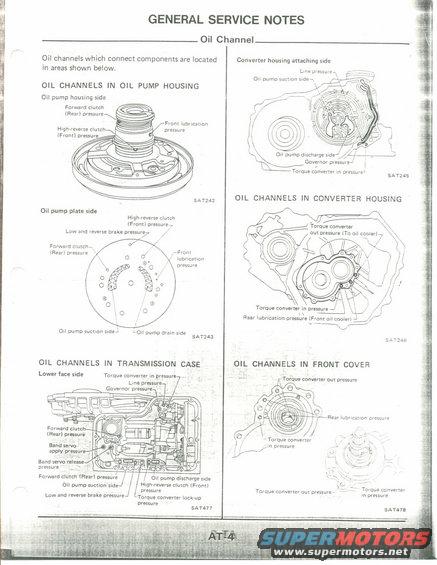
AT-4 oil channel routing diagrams showing line, forward/high-reverse clutch, governor, lubrication and torque converter pressure passages across pump housing, converter housing, case and front cover.
This is page AT-4, "General Service Notes: Oil Channel," from an automatic transmission service manual. It explains that oil channels connecting transmission components are located in the areas shown in six labeled illustrations. The page covers: oil channels in the oil pump housing (pump housing side and pump plate side, figures SAT242 and SAT243), the converter housing attaching side (SAT245), oil channels in the converter housing (SAT246), oil channels in the transmission case lower face side (SAT477), and oil channels in the front cover (SAT478). Each diagram identifies the passages carrying specific hydraulic circuits, including forward clutch (rear) pressure, high-reverse clutch (front) pressure, low and reverse brake pressure, front and rear lubrication pressure, line pressure, governor pressure, band servo apply and release pressure, torque converter in/out pressure (including the line to the oil cooler), torque converter lock-up pressure, and oil pump suction, discharge, and drain passages. A technician can use this page to identify which port or channel corresponds to which hydraulic circuit when disassembling, inspecting, air-checking, or pressure-testing the automatic transmission. No specific vehicle year, model, or engine applicability is stated on the page itself.
Is this accurate? Sign in to help verify it.
Frequently asked questions
- Where are the oil channels located in the oil pump housing?
- The oil pump housing side contains channels for forward clutch (rear) pressure, high-reverse clutch (front) pressure, and front lubrication pressure (figure SAT242); the oil pump plate side additionally shows low and reverse brake pressure, oil pump suction side, and oil pump drain side (SAT243).
- Which pressures pass through the converter housing attaching side?
- Line pressure, oil pump suction side, oil pump discharge side, governor pressure, and torque converter in pressure (figure SAT245).
- What oil channels are in the converter housing itself?
- Torque converter out pressure (to oil cooler), torque converter in pressure, and rear lubrication pressure (front oil cooler), shown in figure SAT246.
- What circuits are identified on the transmission case lower face side?
- Torque converter in pressure, line pressure, governor pressure, forward clutch (rear) pressure, band servo apply and release pressure, oil pump suction and discharge sides, high-reverse clutch (front) pressure, low and reverse brake pressure, and torque converter lock-up pressure (SAT477).
- What passages are in the front cover?
- Torque converter out pressure, torque converter in pressure, and rear lubrication pressure (figure SAT478).
Comments
More from this build











No comments yet.