Home/
Registry/
Nissan/
Micra/
1983-1992/
1990 Nissan Micra/
Photo
supermotors.net/registry/media/194463
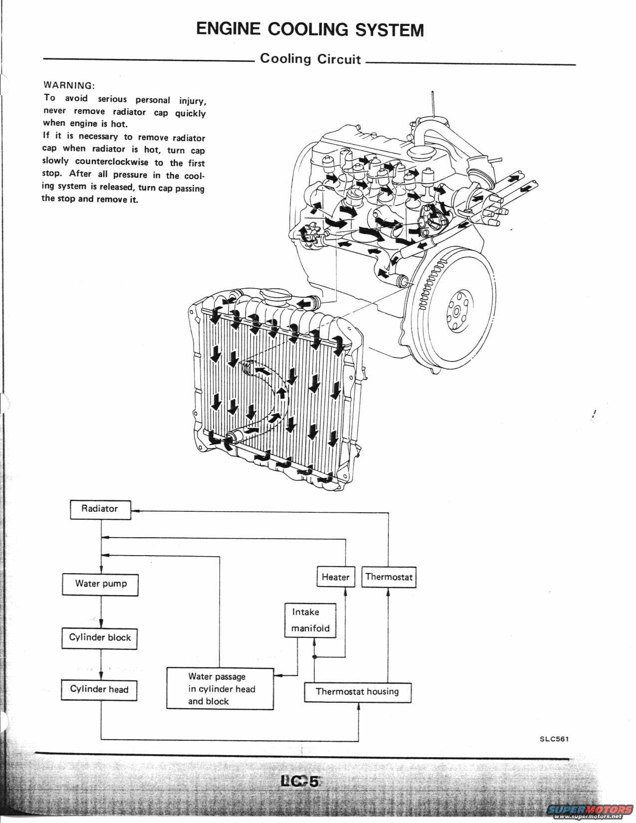
Nissan Micra Engine Cooling System - Cooling Circuit Diagram & Coolant Flow
Reference · 1983-1992 MicraAll 10 schematics
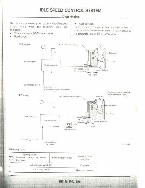
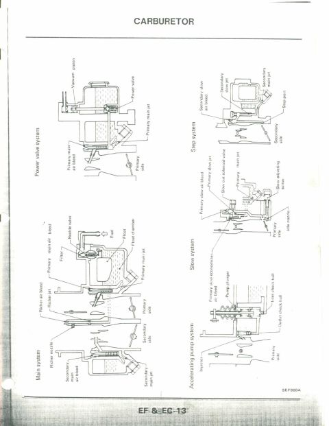
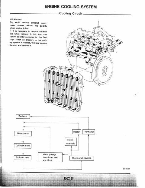
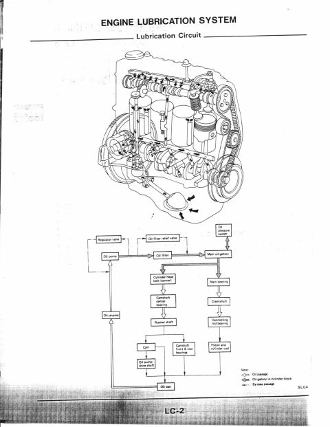


Engine cooling circuit schematic showing coolant flow through radiator, pump, and water passages.
Part of 1983-1992 Nissan Micra Schematics
This is a scanned page from a Nissan service manual covering the Engine Cooling System, specifically the Cooling Circuit (page LC-5, figure reference SLC561). The page contains a safety warning stating that the radiator cap should never be removed quickly while the engine is hot; if removal is necessary while hot, the cap should be turned slowly counterclockwise to the first stop and, only after all pressure in the cooling system is released, turned past the stop and removed. A large illustration shows a cutaway of the engine and radiator with arrows indicating the direction of coolant flow through the engine block, cylinder head, and down through the radiator core. Below the illustration, a block flow diagram maps the coolant circuit: coolant leaves the radiator to the water pump, flows through the cylinder block and cylinder head, through the water passages in the cylinder head and block, then to the intake manifold, heater, and thermostat/thermostat housing before returning to the radiator. The document teaches the reader the overall coolant routing of the engine and safe radiator cap removal procedure. No specific model year, engine designation, or part numbers are printed on this page.
Is this accurate? Sign in to help verify it.
Frequently asked questions
- How should you safely remove a radiator cap when the engine is hot?
- Never remove the cap quickly. If removal is necessary while the radiator is hot, turn the cap slowly counterclockwise to the first stop, wait until all pressure in the cooling system is released, then turn the cap past the stop and remove it.
- What is the coolant flow path shown in the cooling circuit diagram?
- Coolant flows from the radiator to the water pump, through the cylinder block and cylinder head, through the water passages in the cylinder head and block, then to the intake manifold, heater, and thermostat/thermostat housing before returning to the radiator.
- Does the heater core receive engine coolant in this system?
- Yes. The flow diagram shows the heater receiving coolant from the intake manifold/water passages before the flow returns to the radiator.
- What manual page is this cooling circuit information found on?
- The page is labeled LC-5, and the illustration carries the reference SLC561.


No comments yet.