Nissan Automatic Transmission Hydraulic Circuit Diagram - Neutral (N) Range AT-6
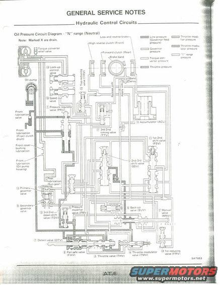
AT-6 oil pressure circuit diagram in N range showing pressure regulator, governor, throttle, shift and lockup control valves with line/governor/throttle pressure paths.
This page, labeled "GENERAL SERVICE NOTES: Hydraulic Control Circuits" (page AT-6, figure SAT653), presents the Oil Pressure Circuit Diagram for the "N" range (Neutral) of a Nissan automatic transmission. A note states that points marked X are drains. A hatching legend distinguishes seven hydraulic pressures: line pressure (governor feed), governor pressure, torque converter pressure, throttle pressure, throttle modifier pressure, throttle modulator pressure, and "1" range pressure. The schematic traces oil flow from the oil pump and torque converter relief valve through numbered valves: (1) pressure regulator valve (PRV), (2) manual valve (MNV) with P R N D 2 1 positions, (3) throttle valve (THV), (4) throttle modulator valve (TMV), (5) pressure modifier valve (PMV), (6) back-up valve (BUV), (7) detent valve (DTV), (8) fail safe valve (FAV), (9) secondary and (10) primary governor valves, (11) 1st-2nd shift valve (FSV), (12) 2nd-3rd shift valve (SSV), (13) 3rd-2nd down shift valve (TDV), (14) 1st reducing valve (FRV), (15) top reducing valve (TRV), (16) accumulator (ACL), (17) 3rd-2nd timing valve (TTV), (18) speed cut valve, and (19) lock-up control valve. Friction elements shown include the high-reverse (front) clutch, forward (rear) clutch, brake band with band servo apply/release sides, and low and reverse brake, plus front and rear lubrication circuits.
Is this accurate? Sign in to help verify it.
Frequently asked questions
- What does this diagram show?
- It is the oil pressure (hydraulic control) circuit diagram for the automatic transmission in the "N" (Neutral) range, from the General Service Notes section, page AT-6, figure SAT653.
- What do the X marks on the diagram mean?
- A note on the diagram states: "Marked X are drain", the X symbols indicate drain points in the hydraulic circuit.
- Which pressures are identified in the legend?
- Line pressure (governor feed pressure), governor pressure, torque converter pressure, throttle pressure, throttle modifier pressure, throttle modulator pressure, and "1" range pressure, each shown with a different hatch pattern.
- What valves are numbered in the hydraulic circuit?
- Nineteen components: (1) pressure regulator valve PRV, (2) manual valve MNV, (3) throttle valve THV, (4) throttle modulator valve TMV, (5) pressure modifier valve PMV, (6) back-up valve BUV, (7) detent valve DTV, (8) fail safe valve FAV, (9) secondary governor valve, (10) primary governor valve, (11) 1st-2nd shift valve FSV, (12) 2nd-3rd shift valve SSV, (13) 3rd-2nd down shift valve TDV, (14) 1st reducing valve FRV, (15) top reducing valve TRV, (16) accumulator ACL, (17) 3rd-2nd timing valve TTV, (18) speed cut valve, and (19) lock-up control valve.
- Which clutches and brakes appear in the circuit?
- The high-reverse clutch (front), forward clutch (rear), brake band with band servo (apply side and release side), and the low and reverse brake.
Comments
More from this build











No comments yet.